Loading...
Loading...
Loading...
Loading...
Loading...
Loading...
Loading...
Loading...
Loading...
Loading...
Loading...
Loading...
Loading...
Loading...
Loading...
Loading...
Loading...
Loading...
Loading...
Loading...
Loading...
Loading...
Loading...
Loading...
Loading...
Loading...
Loading...
Loading...
Loading...
Loading...
Loading...
Loading...
Loading...
Loading...
Loading...
Loading...
Loading...
Loading...
Loading...
Loading...
Loading...
Loading...
Loading...
Loading...
Loading...
Loading...
Loading...
Loading...
Loading...
Loading...
Loading...
Loading...
Loading...
Loading...
Loading...
Loading...
Loading...
Loading...
Loading...
Loading...
Loading...
Loading...
Loading...
Loading...
Loading...
Loading...
Loading...
Loading...
Loading...
Loading...
Loading...
Loading...
Loading...
Loading...
Loading...
Loading...
Loading...
Loading...
Loading...
Loading...
Loading...
Loading...
Loading...
Loading...
Loading...
Loading...
Loading...
Loading...
Loading...
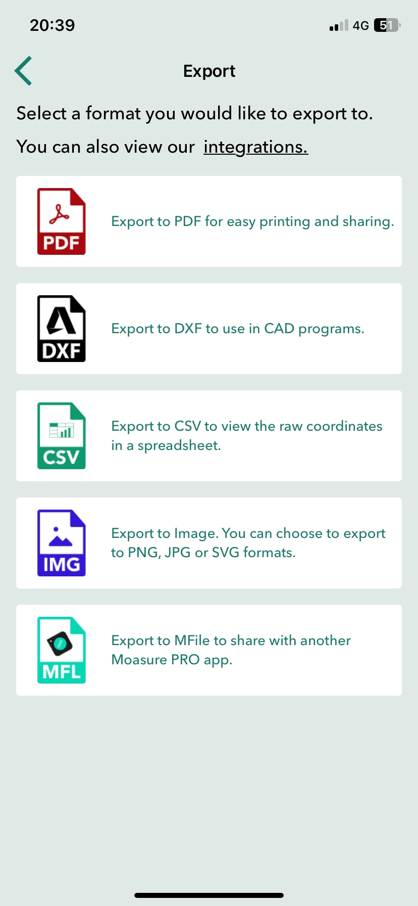
Välkommen till Moasures användarhandbok. Här hittar du all nödvändig information för installation och optimal användning av din nya Moasure-enhet samt funktionerna i Moasure-appen (tidigare känd som Moasure PRO-appen).
Denna instruktionsvideo är utformad för att utrusta dig med kunskap och tekniker som behövs för att få ut det mesta av din Moasure-upplevelse.
Denna guide erbjuder flexibilitet för att tillgodose olika inlärningspreferenser, vilket gör att du kan navigera självständigt genom varje avsnitt och återvända för referens vid behov.
När du använder Moasure-enheten är det viktigt att förstå det tredimensionella koordinatsystemet som hjälper dig att mäta och kartlägga utrymmen. Detta system är baserat på tre axlar: X, Y och Z, tillsammans med vinkelmätningar. Varje mätning består av punkter och kanter. Punkter är platser där du har pausat, och kanter är linjerna som förbinder dessa punkter.
Verktyget Redigera startpunkt låter dig ändra startpunkten för din mätning.
Du kan ändra startpunkt genom att följa stegen nedan:
Tryck på Redigera i navigationsfältet längst ner.
Tryck på Redigera startpunkt i verktygsfältet som öppnas.
Tryck på en ny punkt som du vill använda som startpunkt.
Steg för att ansluta din Moasure-enhet till Moasure-appen
Öppna Moasure-appen på din enhet för att starta anslutningsprocessen.
För Apple/iOS-enheter, ge Bluetooth-behörigheter
För Android-enheter, ge Bluetooth- och platsbehörigheter (plats används för att kalibrera enheten)
Tryck på behörighetsknappen i appen (t.ex. 'Slå på Bluetooth') och tryck sedan på 'Tillåt'. Efter att ha gett behörigheter, tryck på 'Fortsätt'.
Anslut din Moasure-enhet till en strömkälla med USB-kabeln och sätta på den.
Appen kommer automatiskt att söka efter din enhet via Bluetooth. När den har hittats, kommer din enhet att listas under 'Tillgängliga enheter'.
Tryck på din enhet i listan för att ansluta den till Moasure-appen.
Din Moasure-enhet är nu ansluten till appen.
För att säkerställa en smidig anslutning mellan din Moasure-enhet och Moasure-appen, följ dessa steg:
Aktivera Bluetooth: I din enhets inställningar, se till att Bluetooth är aktiverat. Att inaktivera Bluetooth kommer förhindra Moasure-appen från att ansluta till din Moasure-enhet.
Kontrollera appbehörigheter: Om du stöter på anslutningsproblem trots att Bluetooth är aktiverat, kontrollera Bluetooth-behörigheterna för Moasure-appen. Om Bluetooth-behörigheten är inaktiverad för Moasure-appen kommer den inte att kunna ansluta till din enhet. Ge nödvändiga behörigheter för att lösa problemet.
Den här inställningen låter dig dölja Moasure Coach-feedback och anpassa vilken typ av feedback du vill få från coachen.
Moasure Coach är utformad för att hjälpa dig förbättra dina mätningar genom att ge tips och råd om hur du kan förbättra dig. Den markerar också de delar av mätningen som kan förbättras. Om du föredrar att inte se denna feedback kan du stänga av vissa typer av feedback eller helt dölja all feedback.
För att ändra inställningen, följ stegen nedan:
Öppna Inställningar genom att trycka på kugghjulsikonen uppe i högra hörnet.
Tryck på Visningsalternativ.
Tryck på Visa Coach-feedback under Moasure Coach och ställ in detta på nej om du vill dölja all feedback. Om du endast vill dölja viss specifik feedback, lämna detta inställt på ja och tryck istället på Coach-inställningar. Där kan du stänga av den feedback du inte vill ta emot.
Den här inställningen låter dig stänga av det ljud som spelas upp som återkoppling vid mätning.
För att ändra inställningen, följ stegen nedan: 1. Öppna Inställningar genom att trycka på kugghjulsikonen uppe i högra hörnet.
Tryck på Mätningsalternativ.
Aktivera Stäng av mätningsljud under Övrigt.
Den här inställningen låter dig välja mellan ljust eller mörkt tema.
För att ändra den här inställningen, följ stegen nedan: 1. Öppna Inställningar genom att trycka på kugghjulsikonen uppe i högra hörnet.
2. Tryck på Visningsalternativ.
3.Tryck på Temaval under Övrigt. Välj det tema du föredrar (du kan välja mellan ljust och mörkt).
Här kan du lära dig hur du laddar din Moasure-enhet och kontrollerar batterinivån.
Moasure använder det kartesiska koordinatsystemet för att definiera rumsliga relationer och mätningar. Din startreferenspunkt (origo) är din initiala position där:
X = 0
Y = 0
Z = 0 Alla efterföljande mätningar kommer att förhålla sig till denna startpunkt. De två första uppmätta punkterna definierar X-axeln.
Tryck på en punkt för att inspektera eller visa koordinaterna. Koordinaterna är följande:
X: Representerar en horisontell riktning och mäter avstånd och positioner från origo (startpunkten).
Y: Representerar en annan horisontell riktning, vinkelrät mot X-axeln, och mäter avstånd och positioner från origo.
Z: Representerar den vertikala riktningen och mäter höjdskillnader och positioner från origo.
Vinkel: Visar vinkeln mellan kanter eller ytor.
Tryck på en vald kant för att inspektera eller visa längd, höjdskillnad och horisontellt avstånd.
Längd: Det totala avståndet som mäts längs en kant eller linje från en punkt till en annan.
Höjdskillnad: Det vertikala avståndet mellan två punkter, vilket representerar förändringen i höjd (Z-axeln) från startpunkten till slutpunkten.
Horisontellt avstånd: Det horisontella avståndet mellan två punkter, vilket representerar avståndet i horisontell riktning från startpunkten till slutpunkten.
Tryck på Ange startpunkt för att göra den valda punkten till din nya startpunkt.
Kom igång Lär dig hur du monterar och använder Moasure STICK, laddar ner appen och kopplar ihop din Moasure-enhet.
Moasure Lär dig hur du använder Moasure-enheten. Vi går igenom mätteknik, noggrannhet och andra viktiga områden.
Moasure-appen Lär dig hur du använder funktionerna i Moasure-appen, så som redigeringsverktyg, spara och export av mätningar.
Användningsområden Lär dig om vanliga användningsområden för Moasure med mer djupgående guider om hur du mäter upp specifika platser.
As Moasure ONE uses motion sensors such as gyroscopes and accelerometers, care should be taken when rotating the device.
Whenever you need to rotate the device so that the reference point is aligned to your required orientation, you should rotate the device gradually – not suddenly. As with sudden impacts or collisions, abrupt rotations negatively impact the device's sensors which in turn compromises measurement accuracy.
When rotating Moasure ONE, do so gradually from one pause point to another.
I det här avsnittet kommer du att lära dig att bemästra din mätteknik. Avsnittet består av tre delar:
Om du föredrar att läsa istället för att titta, kan du följa länkarna nedan för att läsa mer om hur du bemästrar tempo, placering och rotation.
I den här sektionen kommer vi att visa hur du sparar dina mätningar och hur du håller dem organiserade genom att skapa projektmappar så att du enkelt kan få åtkomst till dem.
När du sparar en mätfil för första gången i din app, följ dessa steg:
Tryck på Arkiv i den nedre navigeringsfältet.
Tryck på Spara.
Ange ett namn för din mätning;
Inställningen för Starttyp av väg anger vilken vägtyp som är förvald för alla mätningar. Detta är den vägtyp som automatiskt väljs när du startar en mätning.
För att ändra denna inställning, följ stegen nedan:
Öppna Inställningar genom att trycka på kugghjulsikonen uppe i högra hörnet.
Stäng-verktyget justerar mätningen genom att flytta start- och slutpunkten till samma position. Det är användbart i situationer där du avsåg att mäta en sluten form och avsluta vid startpunkten, men råkade avsluta på en något avvikande plats.
När mätningen har stängts, byts Stäng-verktyget ut mot ett Öppna-verktyg, som gör motsatsen – det separerar start- och slutpunkten igen.
Så här använder du verktyget Stäng/Öppna:
Tryck på Redigera
Tryck på Stäng/Öppna
Den här inställningen låter dig inaktivera insamling av analysdata. Analys är aktiverat som standard.
För att ändra den här inställningen, följ stegen nedan:
Öppna Inställningar genom att trycka på kugghjulsikonen uppe i högra hörnet.
Ta bort en Moasure-enhet.
För att ta bort en Moasure-enhet, följ stegen nedan:
Öppna Inställningar genom att trycka på kugghjulsikonen uppe i högra hörnet.
Tryck på Kontohantering och enhetshantering.
Tryck på Enhetsinställningar under Enhetshantering.
I layoutläget guidar Moasure dig till angivna punkter via Moasure-appen, vilket möjliggör identifiering av platser och markeringar.
Förutom att du kan kan du också börja sätta ut direkt från ett sparat mätresultat.
I Moasure-appen, tryck på Arkiv > Öppna, och öppna sedan en mapp vid behov. När du har hittat ditt mätdiagram, tryck på de tre vertikala prickarna och välj Starta layoutläge.
Detta öppnar ditt mätdiagram direkt i layoutläget, där du kan förhandsgranska det område du vill sätta ut.
Välj en annan Moasure-enhet i ditt konto.
Du kan ha flera Moasure-enheter registrerade under ett och samma konto och enkelt växla mellan dem vid mätningar.
För att byta Moasure-enhet, följ stegen nedan:
Öppna Inställningar genom att trycka på kugghjulsikonen uppe i högra hörnet.
Tryck på Kontohantering och enhetshantering.
Tryck på
Skicka en supportförfrågan via appen.
Du kan kontakta oss via appen eller via [email protected]. Vi rekommenderar att du skickar din supportförfrågan via appen, eftersom det då skickas diagnostik- och mätdata som gör att vi kan hjälpa dig på bästa sätt.
För att skicka en supportförfrågan via appen, följ stegen nedan:
Öppna Inställningar genom att trycka på kugghjulsikonen uppe i högra hörnet.
Tryck på Skicka supportförfrågan.
Tryck på Aktivera analys under Kontohantering.
Välj önskat värde (ja/nej).
Välj önskat mätsystem genom att trycka på det. Du kan välja mellan metriskt och imperiskt system.
Du kan ändra inställningarna för decimalnoggrannhet, det vill säga antalet siffror i ett tal, för följande enheter:
Längd (meter/fot)
Yta (kvadratmeter/kvadratfot)
Vinkel (grader)
Lutning (procent)
Export (meter/fot, vilket kan ställas in separat från längdinställningen så att exporten visas annorlunda än mätningen i appen)
Tryck på Ta bort enhet.
Bekräfta att du vill ta bort enheten genom att trycka på Ja i dialogrutan som visas.
Du kommer att se en lista över enheter. Den valda enheten kommer att ha en bock i nedre högra hörnet av Moasure-ikonen. Tryck på en annan enhet för att byta till den.
E-postmeddelandet skickas via telefonens standard-e-postklient. Bekräfta att du vill skicka meddelandet via din e-postapp. När detta är gjort skickas din förfrågan och du kommer att omdirigeras tillbaka till appen.
Tryck på Starttyp av väg och välj den vägtyp du önskar ska vara förvald.
Öppna Inställningar genom att trycka på kugghjulsikonen uppe i högra hörnet.
Tryck på Mätningsalternativ.
Aktivera Automatisk ignorering av punkter under Automatisk redigering.
Om alternativet Starta layoutläge är nedtonat betyder det antingen att den valda mätningen inte är kompatibel med layoutläget, eller att du inte har en Moasure 2 PRO kopplad till din app.
Lär dig hur du lägger till ett rutnät på arbetsytan för att få en visuell referens för skala, vilket är användbart vid granskning av mätningar.
Öppna Inställningar genom att trycka på kugghjulsikonen.
Tryck på Visningsalternativ.
Tryck på Rutnätsformat (2D).
Välj önskat rutnätsformat: a. Inget rutnät b. Markplan (ingen skala) c. Huvudlinjer d. Huvud- och hjälplinjer
En grön bock visas bredvid det valda rutnätsformatet.
Tryck på bakåtpilen uppe till vänster för att återgå till arbetsytan
Rutnätsalternativen förbättrar visualiseringen och användarvänligheten vid mätningar genom att ge en snabb referens till den faktiska storleken på det uppmätta området. Denna funktion är användbar för användare som behöver en tydlig visuell indikation på skalan i sin mätmiljö.
Moasure has an App Link / Deep Link API that allows partners to build deep link functionality. This allows partners to, for example, create a button in their app to start a measurement which on tap will open the Moasure app and start a measurement straight away. Once the action is completed, the Moasure app will then redirect the user to the partner app with the relevant data that can then be parsed by the partner app. There are also other operations supported.
To access the API, please contact [email protected].
Inställningen för frånkoppling av enheten avgör hur länge det dröjer innan Moasure-enheten kopplas från och stängs av.
Moasure-enheten stängs normalt av inom en minut om du slår på den utan att påbörja en mätning, för att spara batteri. Du kan justera denna tidsgräns via inställningarna.
Följ stegen nedan för att ändra inställningen:
Öppna Inställningar genom att trycka på kugghjulsikonen uppe i högra hörnet.
Tryck på Mätningsalternativ.
Tryck på Moasure-enhetens frånkopplingstid och välj önskat värde. Du kan välja mellan: en minut, två minuter eller fem minuter.
Seamlessly import your measurements from Moasure into ArcSite with a single tap. Using ArcSite you can take your measurements and turn them into a fully priced customer proposal in minutes.
View the official guide on https://www.arcsite.com/integrations/moasure.
Använd detta för att återställa appens inställningar till standardvärden. Dina mätningar kommer inte att raderas.
tryck på Inställningar genom att trycka på kugghjulsikonen uppe i högra hörnet.
Tryck på Kontohantering och enhetshantering.
Tryck på Återställ inställningar.
Bekräfta att du vill genomföra återställningen genom att trycka på Återställ i dialogrutan som visas.
Moasure does not yet have a public facing web service API. If you are interested in this, we would like to hear from you. Contact us at [email protected].
Använd detta när du vill logga ut från ditt Moasure-konto.
För att logga ut, följ stegen nedan:
Öppna Inställningar genom att trycka på kugghjulsikonen uppe i högra hörnet.
Tryck på Kontohantering och enhetshantering.
Tryck på Logga ut under Kontohantering.
Tryck på Standard och spara din mätning inom ett befintligt projekt. Alternativt kan du skapa en ny projektmapp genom att trycka på knappen "Lägg till projekt" för att hålla dina mätningar organiserade.
Observera: Om du öppnar din sparade fil och stänger den utan att göra några ändringar, kommer du inte att få en uppmaning att spara och ingenting kommer att ha ändrats. Om du däremot öppnar filen och gör ändringar, får du två alternativ: Spara och Spara som. Genom att välja Spara skrivs den befintliga filen över med de aktuella ändringarna, medan Spara som låter dig spara den befintliga filen och skapa en ny version genom att ange ett nytt mät-namn och mapp.
Denna uppmaning visas efter att ha gjort ändringar och utfört åtgärder som potentiellt kan leda till dataförlust, såsom att öppna en fil, göra redigeringar och initiera en ny mätning. Den ger flexibilitet och kontroll över din filhanteringsprocess.
Det finns olika färger som kan visas på din Moasure LED-indikator.
Beroende på sammanhanget kan dessa betyda olika saker, både under mätning och när ingen mätning pågår.
Blinkande blått – Den blinkande blå LED-indikatorn visas när din Moasure-enhet är påslagen och väntar på en Bluetooth-anslutning
Blinkande blått och rött – Den blinkande blå och röda LED-indikatorn visas när din Moasure-enhet är påslagen och väntar på en Bluetooth-anslutning med låg batterinivå.
Stigande och fallande blått – Den stigande och fallande blå LED-indikatorn visas när din Moasure-enhet är ansluten till Bluetooth.
Stigande och fallande blått och rött – Den stigande och fallande blå och röda LED-indikatorn visas när din Moasure-enhet är ansluten till Bluetooth med låg batterinivå.
Fast rött – En fast röd LED-indikator betyder att Moasure är i ett 'Väntar på att fånga'-läge. Detta innebär att din enhet är redo att placeras vid din startpunkt och hållas stilla i ungefär en sekund. När enheten är stilla kommer en mätpunkt att fångas.
Fast grönt – En fast grön LED-indikator indikerar ett 'Framgång'-läge. När den gröna LED-indikatorn aktiveras under en mätning betyder det att en mätpunkt har fångats – du kan nu fortsätta mäta eller avsluta mätningen om den är klar.
Blinkande grönt – En blinkande grön LED-indikator aktiveras när du börjar förflytta dig med din Moasure. Detta betyder att enheten mäter sin egen rörelse och registrerar data. LED-indikatorn fortsätter att blinka grönt i upp till 6 sekunder med Moasure 2/Moasure 2 Pro och upp till 12 sekunder med Moasure 2 Pro, beroende på .
Blinkande gult – En blinkande gul LED-indikator aktiveras under rörelse, där LED-indikatorn börjar blinka gult mellan 6 och 9 sekunder med Moasure 2 och mellan 12 och 18 sekunder med Moasure 2 Pro, beroende på .
Blinkande gult indikerar att du snart behöver hitta en pauspunkt, annars riskerar LED-indikatorn att övergå till en blinkande röd LED.
Blinkande rött – Varning: En blinkande röd LED-indikator aktiveras under rörelse, där LED-indikatorn börjar blinka rött efter 9 sekunder med Moasure 2 och efter 18 sekunder med Moasure 2 Pro, beroende på .
PAUSA NU: Varning – En blinkande röd LED betyder att din mätning tar för lång tid. Du måste undvika den blinkande röda LED-indikatorn, eftersom det ökar risken för mätfel. Placera alltid Moasure medan LED-indikatorn blinkar grönt och senast när LED-indikatorn blinkar bärnstensfärgat.
4 gula blinkande signaler – Laddar batteri: 0% - 25%
1 grön följt av 3 gula blinkningar – Laddar batteri: 26% - 50%
2 gröna blinkningar följt av 2 gula blinkningar – Laddar batteri: 51% - 75%
3 gröna blinkningar följt av 1 gula blinkning – Laddar batteri: 76% - 99%
Fast grönt – Batteriet är fulladdat
4 röda blinkningar – Laddningsfel: Batteriet är antingen för varmt, för kallt eller defekt. Se till att ladda vid rumstemperatur
Blinkande blått – Den blinkande blå LED-indikatorn visas när din Moasure-enhet är påslagen och väntar på en Bluetooth-anslutning.
Långsamt blinkande blått – Den långsamt blinkande blå LED-indikatorn visas när din Moasure-enhet är ansluten till en Bluetooth-anslutning.
Fast rött – En fast röd LED-indikator betyder att Moasure är i ett 'Väntar på att fånga'-läge. Detta innebär att din enhet är redo att placeras vid din startpunkt och hållas stilla i ungefär en sekund. När enheten är stilla kommer en mätpunkt att fångas.
Fast grönt – En fast grön LED-indikator indikerar ett 'Framgång'-läge. När den gröna LED-indikatorn aktiveras under en mätning betyder det att en mätpunkt har fångats – du kan nu fortsätta mäta eller avsluta mätningen om den är klar.
Blinkande grönt – En blinkande grön LED-indikator aktiveras när du börjar förflyttar dig med Moasure. Detta betyder att din enhet mäter sin egen rörelse och registrerar data. LED-indikatorn fortsätter att blinka grönt i upp till 6 sekunder.
Blinkande gult – En blinkande bärnstensfärgad (orange) LED-indikator aktiveras under rörelse, där LED-indikatorn börjar blinka bärnstensfärgat mellan 6 och 9 sekunder.
Pausa nu: Blinkande gult indikerar att du snart behöver hitta en pauspunkt, annars riskerar LED-indikatorn att övergå till en blinkande röd LED. Sikta på att placera enheten ner på eller före 8 sekunder.
Blinkande röd – Varning: En blinkande röd LED-indikator aktiveras under rörelse och börjar blinka rött efter 9 sekunder.
PAUSA NU: Varning – En blinkande röd LED betyder att din mätning tar för lång tid. Du behöver undvika den blinkande röda LED-indikatorn då det ökar risken för mätfel. Placera alltid Moasure medan LED-indikatorn blinkar grönt och senast när den blinkar gult.
Blinkande gult – Batteriet laddas
Fast grönt – Batteriet är fulladdat
1 rött blink följt av 2 gula – Låg batterinivå
3 röda – Fel: Kontakta [email protected]
Verktyget Redigera etikett låter dig lägga till text vid pauspunkter – detta är användbart för identifiering och demonstrationsändamål.
Utöver möjligheten att lägga till anteckningar på arbetsytan kan du även lägga till etiketter vid pauspunkter medan du mäter, och när du har slutfört din mätning.
Varje gång din Moasure-enhet står stilla efter att ha flyttats registrerar den en pauspunkt. När du stannar vid din första pauspunkt visas en pennikon på arbetsytan.
När du står stilla vid en pauspunkt, tryck på pennikonen.
Tryck på mikrofonikonen.
Säg etikettens namn högt medan du står stilla.
Tryck på mikrofonikonen igen för att stoppa inspelningen, eller fortsätt mäta så stoppas röstinspelningen automatiskt.
Etiketten läggs till vid den senaste pauspunkten.
Den etiketterade pauspunkten blir orange på arbetsytan.
När du står stilla vid en pauspunkt, tryck på pennikonen.
Tryck på textikonen.
Ange etikettnamnet i textrutan.
Tryck på Verkställ för att bekräfta, eller Avbryt för att ta bort etiketten och återgå till din mätning.
Du kan även lägga till etiketter efter att mätningen är avslutad – följ stegen nedan:
Öppna den sparade mätfilen.
Tryck på den punkt du vill märka.
Tryck på Redigera.
Bläddra bland alternativen och tryck på Etikett.
Etiketten visas nu på skärmen. När du trycker någon annanstans i mätningen döljs texten, men den etiketterade punkten förblir synlig och är markerad med orange färg.
För att ta bort en befintlig etikett, följ dessa steg:
Tryck på en punkt med etikett i mätningens diagram för att markera den.
Etiketten visas tillsammans med en papperskorgsikon.
Tryck på papperskorgsikonen för att ta bort etiketten.
Med Moasure 2 Pro kan du välja ditt föredragna mätningsläge för att bäst passa dina behov:
Högsta noggrannhet (6–8 sekunder) maximal precision med kortare intervall mellan pauspunkterna.
Längsta mättid (12–16 sekunder) längre intervall mellan pauspunkterna med reducerad noggrannhet.
Pausa var 6–8 sekund (Pausa inom den gröna zonen och senast i den gula zonen).
För användare som prioriterar hög noggrannhet vid mätning.
Pausa var 12–16 sekund (Pausa inom den gröna zonen och senast i den gula zonen).
Låter dig gå längre mellan pauspunkterna.
Reducerad noggrannhet jämfört med högsta noggrannhet.
För att uppnå maximal noggrannhet i alla rörelsebaserade mätningar, följ dessa tre viktiga tekniker:
Tempo: Gå i ett snabbt tempo mellan mätpunkterna (pauspunkterna).
Placering: Placera Moasure-enheten snabbt och försiktigt utan att sväva över ytan.
Rotation: Rotera enheten gradvis, inte abrupt, för att undvika att störa sensorerna.
För att ändra din Mättid / Noggrannhet, följ dessa steg:
Tryck på kugghjulet i det övre högra hörnet av appen.
Tryck på Mätningsalternativ.
Tryck på Mättid under rubriken Mättid / Noggrannhet.
Välj om du vill ha högre noggrannhet eller längre tid mellan pauserna.
Referenspunkten är där din Moasure-enhet mäter ifrån. Som standard är mätreferenspunkten den skarpa hörnspunkten på motsatt sida av LED-indikatorn.
Om du använder din Moasure-enhet med Moasure STICK behöver du flytta mätreferenspunkten till framdelen av höljet för att upprätthålla noggrannheten i dina mätningar.
För att göra detta, följ dessa steg:
Gå till Inställningsmenyn (tryck på kugghjulet i det övre högra hörnet av appen);
Tryck på Mätningsalternativ;
Aktivera Använd Moasure STICK-tillbehöret.
I denna guide får du lära dig hur du använder verktyget Lägg till djup, som gör det möjligt att beräkna hur mycket material som behövs för att täcka en yta med ett specifikt tillagt djup.
Verktyget Lägg till djup kan användas för att lägga till ett anpassat djup till en yta. Det är användbart i scenarier såsom att beräkna hur många kubikmeter täckmaterial (t.ex. bark) som behövs för en sluttande trädgård. Volymen beräknas genom att multiplicera det tillagda djupet med ytan (vilket är summan av arean av alla ytor i den tredimensionella figuren). Ytan förändras när djup läggs till, eftersom den kopierade ytan flyttas uppåt eller nedåt. Den resulterande volymberäkningen baseras på en vertikal projektion till den nya nivån.
Verktyget är användbart för trädgårdsanläggare eller landskapsarkitekter som planerar täckmaterial, men också för markläggare som förbereder grund- eller bärlager för gångar och uteplatser. Låt säga att en trädgårdsanläggare vill veta hur mycket täckmaterial som behövs för att täcka en yta med ett djup på 15 cm. Eller att en markläggare vill skapa ett 15 cm djupt lager av grus som underlag för marksten eller betong. Genom att ta ytan och multiplicera den med 15 cm får man volymen av material som krävs. Verktyget Lägg till djup förenklar detta genom att förberäkna ytan och erbjuda verktyg (såsom ett reglage) för att ange önskat djup, vilket resulterar i en volymberäkning.
För att använda verktyget Lägg till djup, följ dessa steg:
Öppna appen och tryck på Redigera.
Välj Lägg till djup.
Du kommer då till skärmen för Lägg till djup, där du ser:
Volymen efter tillagt djup (initialt inställd på 0).
Det djup du har angett.
När du justerar reglaget kommer du att se att volymen ändras i takt med det tillagda djupet. Volymen beräknas baserat på en vertikal projektion till en kopierad yta vid den nya nivån. Enkelt uttryckt: det tillagda djupet multipliceras med ytan, där ytan är summan av alla ytor i den tredimensionella figuren.
Till exempel, om du vill ta reda på hur många kubikmeter täckmaterial (t.ex. bark) som behöver läggas till, kommer den volym som beräknas med detta verktyg att ge dig det värdet.
Moasure STICK-fäste är en inställning som låter Moasure-appen veta att du använder Moasure STICK
Om du vill använda Moasure STICK för att mäta rekommenderar vi att du meddelar detta i Moasure-appen – detta hjälper till att maximera noggrannheten.
Referenspunkten på din Moasure-enhet är placerad på undersidan av det vassa hörnet. När du har meddelat i appen att du använder Moasure STICK, flyttas referenspunkten till spetsen av den skumfodrade hållaren.
Öppna Inställningar genom att trycka på kugghjulet uppe i högra hörnet.
Tryck på Mätningsalternativ.
Tryck på Använd Moasure STICK-fäste.
Välj "Ja".
flyttas nu till spetsen av STICK-hållarens skumfodrade ände.
Räta upp-verktyget låter dig justera vinklarna i din mätning. Det är användbart vid rumsuppmätningar där väggar och hörn ska justeras till 90° eller 45°. Du kan välja mellan tre intensitetsnivåer
Låg
Medel
Hög
För att använda verktyget:
Tryck på Redigera
Tryck på Räta upp
Välj önskad intensitet
Verktyget "Redigera Bakgrund" gör det möjligt för dig att lägga till en bakgrundsbild till din mätning.
Verktyget "Redigera Bakgrund" kan användas för att visa kunder eller kollegor en visualisering av det uppmätta projektet i relation till ett fotograferat område, eftersom mätningen då läggs ovanpå bakgrunden.
Lägg till Bakgrundsbild
Tryck på Redigera i den nedre navigeringslisten för att öppna Redigeringsverktygsfältet.
Tryck på Redigera Bakgrund.
Tryck på Lägg till Bild som finns i sidfoten längst ner.
En galleri kommer att visas som låter dig välja en bild från din telefon att använda som bakgrund. När du har valt en bild kommer den att laddas upp till appen och användas som din bakgrund.
När du har lagt till en bild som bakgrund kan du redigera bilden. Följande bildredigeringsverktyg är tillgängliga:
Rotera (roterar bakgrundsbilden med +90° grader). För att rotera bilden, tryck på roteraikonen i det övre högra verktygsfältet.
Zooma (zoomar in/ut på bakgrundsbilden). För att zooma, nypa genom att flytta ditt pekfinger och tumme upp och ner.
Dra (drar bakgrundsbilden åt vänster eller höger). För att dra, tryck på bilden med ditt pekfinger och flytta den åt vänster eller höger.
Beskära (beskär bakgrundsbilden). För att beskära, tryck på beskärningsikonen i det övre högra verktygsfältet. Vita kanter visas; allt utanför dessa kanter kommer att beskäras.
By default the background image is selected, you can however also rotate, drag and zoom the measurement drawing. To do so, select the measurement drawing by tapping on the measurement icon in the right bottom. You can then rotate, drag and zoom the measurement drawing relative to the background image by using touch gestures. You can always switch back to the background image again to continue editing the background image.
Learn how to measure interior and exterior staircases.
Follow these steps to measure a staircase: 1. You can start a closed shape measurement by tapping on '+' in the bottom centre of the app and choosing Closed Shape. A closed shape will provide the perimeter as well as the square footage/square meters. 2. In the following screen, you can start measuring. At the bottom, you will see the available path types. By default, the path type it will measure in is 'Straight Line'. This means that the pause points (the points at which you place the device down) are connected by a straight line. You can leave it on Straight Line. 3. Choose a memorable start point at the bottom of your staircase, for example at the left bottom of the staircase. Place your device stationary at that start point to record your first measurement point.
4. Walk up the stairs and stick to the side you've chosen (e.g. if you started on the left, stick to the left) and place the device down every 6-8 seconds. There's no rush in getting to a specific point, you can pause as many times as you want/need. 5. Once at the top, pause to record that measurement point and then move to the other side of the staircase (for example right) and place the device down to capture the furthest point on the other side of the staircase. 6. Walk down the staircase and repeat step 4 (stopping every 6-8 seconds by placing the device down making sure it is stationary). 7. Once you reach the bottom, stop again. 8. Now walk to the other side to finish at the same point where you started so that the shape is closed. 9. Tap the red stop icon at the bottom of the screen to complete your measurement. You will now see the 2D 'plan view' of the drawing that you have captured which shows a top-down perspective of your measurement where you can see the perimeter and area of the staircase. By tapping on the 3D cube, you can explore elevations, grades, or gradients. Tapping each selected point reveals their relative XYZ coordinates, with Z showing the height elevation. By tapping on a selected edge, you can view the length, rise and run. Read more about inspecting point coordinates and understand views.
Lägg till en Moasure-enhet
Du kan ha flera Moasure-enheter registrerade under ett och samma konto och enkelt växla mellan dem vid mätning.
För att lägga till en Moasure-enhet, följ stegen nedan:
Öppna Inställningar genom att trycka på kugghjulsikonen uppe i högra hörnet.
Tryck på Kontohantering och enhetshantering.
Tryck på Enhet under Enhetshantering.
Tryck på Lägg till enhet.
Följ instruktionerna på skärmen för att para ihop din enhet. Du kan läsa mer om ihopkoppling i vår guide .
När den här inställningen är aktiverad läggs Moasure-modulikoner till i mätningen för att visa hur enheten var orienterad vid placering.
För att ändra den här inställningen, följ stegen nedan:
Öppna Inställningar genom att trycka på kugghjulsikonen uppe i högra hörnet.
Tryck på Visningsalternativ.
Tryck på Visa/Dölj moduler i ritningar under Inställningar för skärmen.
Välj önskat värde (ja/nej).
Scribe changes the way floorplans are drawn and used. By sharing a URL, anyone can access the floorplan, and then inspect the property in 3D. Whilst exploring a property in 3D, you can change the style of the interior of the property, attach notes to elements within the property and breakdown area calculations. The floorplan has become far more than just a static image and now it is a proper digital twin of a property.
Moasure ONE lets you measure circles and arcs with ease. Watch our quick video tutorial to learn how to measure circle radius, diameter, circumference and even calculate area.
Capture 3 or more points around a circle to measure the radius, diameter, circumference or the area of a circle. Arc Path Type enables you to measure arc length, arc angle and segment area just as easily.
Collect at least 3 points on the edge of the circle or arc
All points must be on the circumference or the edge of the arc
Spread your points across as much of the perimeter of circle
Use the Wall Path Type to rapidly measure building footprints or rooms.
Lär dig mer om de sju olika mätvägstyperna du kan välja mellan när du använder din Moasure-enhet, hur du växlar mellan dem samt hur du ändrar din startvägtyp.
Ignorera automatiskt är ett verktyg som gör det möjligt att automatiskt ta bort oönskade punkter längs en rak linje.
När du sätter ned din Moasure-enhet under en mätning med 6 till 8 sekunders mellanrum, registrerar Moasure-appen en punkt – en datakoordinat med X-, Y- och Z-värden.
Verktyget Ignorera automatiskt gör det möjligt att "ignorera" eller inaktivera punkter som ligger på samma plan. När en punkt ignoreras kopplas linjen automatiskt mellan punkten före och efter den ignorerade punkten, vilket ger en rak linje och motsvarande mätresultat.
Verktyget Redigera linjer låter dig ändra den typ av som ursprungligen mättes.
Du kan till exempel ändra en rak linje till en spårningslinje eller en ignorerad linje till en rak linje. Du kan även skapa en cirkel eller båge baserat på två linjer och en punkt.
Förutom att ändra linjetyp kan du även dela upp eller slå ihop linjer. Om du exempelvis har gjort en mätning med fyra segment i rak linje, kommer Edit Paths att visa dem som en sammanhängande linje. Du kan då dela upp linjerna vid varje pauspunkt för att redigera dem separat – så att du exempelvis kan ändra en linje till spårning och behålla de andra som raka linjer.
Anteckningsfunktionen låter dig lägga till fria textanteckningar var som helst på arbetsytan, utan att koppla dem till en specifik mätpunkt.
Utöver att lägga till på enskilda punkter kan du också placera anteckningar direkt på arbetsytan för att ge extra sammanhang, markera specifika områden eller dokumentera observationer. Detta är användbart för att markera delar av en lekplats, identifiera risker eller notera funktioner på platsen som kräver uppmärksamhet.
Anteckningar kan hjälpa till att göra mätningar tydligare och enklare att förstå när de delas med kollegor, entreprenörer eller kunder.
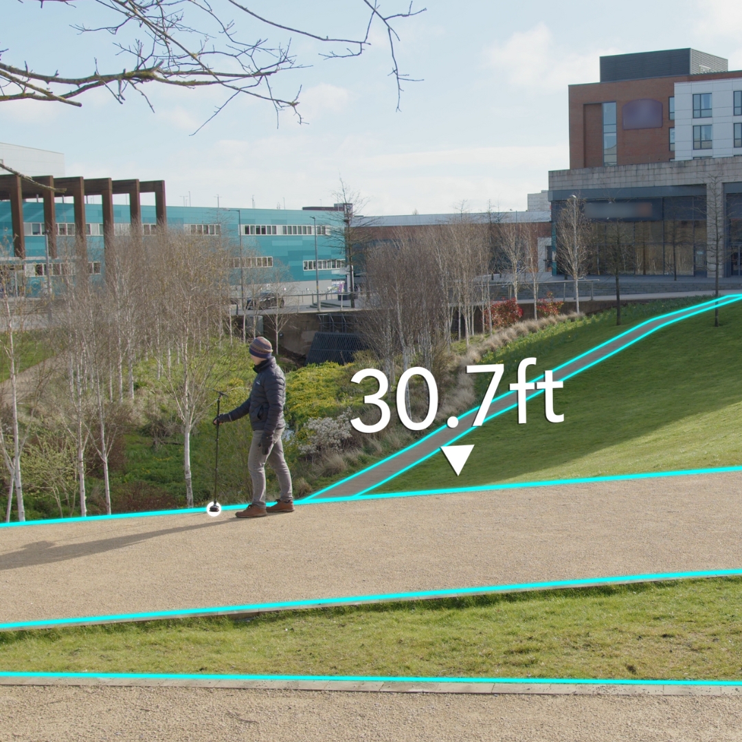
Learn how to measure elevation, slope, rise/run and gradient.
Moasure ONE uses high performance inertial sensors to record changes in its own position as it moves from one point to another. Moasure ONE measures in 3D by default, so it will always automatically capture elevation changes, slope and rise and run / rise and fall. To view measurements in 3D, you can switch to. To view rise and run, rise and fall, slope and gradient, you can use the Tool. The elevation is measured relative to the starting point, which is the origin (x:0, y:0, z:0). The elevation can be positive (upwards) and negative (downwards). The elevation captured depends on the used for the measurement. When using Straight Line, elevation is measured in a straight line between the two points and elevation changes between the pause points (in-flight) are disregarded. In Trace Line, elevation changes are captured in-flight which means that you see exactly how the device has moved up or down in between the pause points.
Läs om vilken data vi lagrar när du skapar ett konto och hur du raderar ditt konto, vilket anonymiserar all data som är kopplad till ditt konto.
När du registrerar ett konto i Moasure-appen lagrar vi ditt namn och din e-postadress.
Mätningar, bakgrundsbilder och kontoprofilbilder/logotyper lagras på din enhet och delas inte med eller är åtkomliga för 3D Technologies / Moasure.
För att förbättra användarupplevelsen och i forskningssyfte samlar vi viss data om hur appen används. Du kan dock . Observera att analysdata hjälper oss att ge dig bättre support vid ärenden.
För att radera ditt konto, följ stegen nedan:
Denna steg-för-steg-guide visar hur du noggrant kan mäta ett bostadshus och en bakgård med hjälp av Moasure. Lär dig hur du använder lager för att fånga viktiga element, inklusive husets fotavtryck, bakgården, poolen och sprinklers placeringar. Guiden täcker även hur du beräknar yta och märker ut sprinklerpunkter.
Ändra uppstartsmetod från dubbeltryck till rotation eller vice versa.
Moasure stöder två sätt att slå på enheten. En äldre metod, Dubbeltryck, innebär att du dubbeltrycker på enheten för att slå på den. En ny metod, Rotation, innebär att du håller enheten vertikalt och roterar den 180 grader och tillbaka. Läs mer om att slå på din Moasure-enhet i vår guide: .
För att ändra uppstartsmetod, följ stegen nedan:
Inställningen Automatisk upprätning kommer automatiskt att tillämpa verktyget Räta upp på alla mätningar.
Öppna Inställningar genom att trycka på kugghjulsikonen uppe i högra hörnet.
Tryck på
Verktyget Beräkna hörn extrapolerar automatiskt ett hörn baserat på vinklarna mellan mätsegmenten. Det är särskilt användbart när du inte kan nå ett hörn under själva mätningen.
Om du till exempel inte har tillgång till ett hörn i ett rum eller en trädgård, kan du använda Beräkna hörn när mätningen är klar – då beräknar Moasure hörnet åt dig.
Låt oss säga att vi vill beräkna ytan och omkretsen av en trädgård, men att vi inte kan nå ett av hörnen eftersom det finns ett hinder i vägen.
Learn how to measure through or around obstacles and obstructions with Moasure.
Watch this quick tutorial video on how to utilize both the Ignore tool and the Extrapolate Corner tool to measure complex spaces.
Obstacles or obstructions may seem like a challenge when measuring with Moasure, since motion-measuring requires you to pause every 8 seconds.
However, the Moasure app the powerful Ignore tool within the Moasure app offers you a quick and simple way to measure through obstacles as if they never existed.
In the following example, the back yard has large solar panels situated along the perimeter, preventing us from taking a measurement along the very edge of the lawn.
Thanks to the powerful Ignore tool within the Moasure app, we are able to instead measure around the obstacle, capturing points as we go, until we get to the other side of the obstacle. Then, once we've returned to the measurement start point to complete the measurement of the space, we're able to utilize the Ignore tool to remove unwanted points from the measurement drawing.
Optimises cut plans to minimise roll waste.
Options to specify layout direction & seam locations.
Calculate required product quantities.
Create professional quotes & capture customer signatures onsite.
Spend less time measuring up and more time closing your customer.
Measure up a floorplan with Moasure.
Drag & drop flooring products to specific areas.
Calculate product quantity, layout direction, seam locations & waste optimisation.
Create professional quotes & capture customer signatures.
Create work orders with installation diagrams.
Bid Professionally And Profitably Create professional bid packages and pricing options with protected profit.
Instant Waste Optimization Auto find minimum waste layouts & build cut sheets - instantly.
Field And Office Collaboration MeasureSquare's M2 Cloud enables office and showroom collaboration with field reps to serve customers faster.
Ladda Moasure-enheten
Slå på/av enheten
Förstå LED-indikatorer
Förstå referenspunkten
Förstå noggrannheten
Mätningsteknik
Uppdatera firmware
Öppna Inställningar i Moasure-appen genom att trycka på kugghjulsikonen uppe i högra hörnet.
Tryck på Kontohantering och enhetshantering.
Tryck på Radera konto.
Bekräfta att du vill genomföra borttagningen genom att ange ditt lösenord i dialogrutan som visas och trycka på Radera.
När du har slutfört ovanstående steg anonymiseras all data som är kopplad till ditt konto, inklusive ditt namn och din e-postadress.
Om du har problem med att radera kontot, kan du kontakta support på [email protected] med en begäran om dataradering, så hjälper vi dig att ta bort kontot.
Öppna Inställningar genom att trycka på kugghjulsikonen uppe i högra hörnet.
Tryck på Kontohantering och enhetshantering.
Tryck på Enhetsinställningar under Enhetshantering.
Slå på din Moasure-enhet. Enheten måste vara påslagen för att du ska kunna göra ändringar. När enheten är ansluten visas dess data på skärmen.
Tryck på din nuvarande uppstartsmetod och ändra till önskad metod.
Aktivera Automatisk upprätning under Automatisk redigering.
Etiketten läggs automatiskt till vid den aktuella pauspunkten, om inte en tidigare pauspunkt valts innan du tryckte på etikettknappen.
Den etiketterade pauspunkten blir orange på arbetsytan.
Ange önskad text.
Tryck på Verkställ.


Tryck på Redigera.
Tryck på Anteckna.
Skriv in din anteckningstext och tryck på Verkställ när du är klar.
Dra med ett finger för att flytta anteckningen till önskad plats.
Nyp med två fingrar för att ändra storlek och rotera anteckningen.
Tryck var som helst på arbetsytan för att avmarkera och låsa anteckningen på plats.
Anteckningar förblir läsbara även när mätningen roteras.
Tryck en gång på anteckningen.
Tryck på Redigera → Anteckna.
Redigera texten och tryck på Verkställ för att spara ändringarna, eller använd papperskorgsikonen för att ta bort den.
Anteckningar kan läggas till i 2D-anpassad vy och planvy, och är synliga i både 2D- och 3D-vyer.
De stöds för närvarande inte i höjdkurvs- eller ytnätsvyer.
Anteckningar inkluderas när du exporterar till CAD och PDF.


Ändra opacitet (ändrar opaciteten/transparensen hos bakgrundsbilden). För att ändra opacitet, tryck på opacitetsikonen i det övre högra verktygsfältet och dra sedan reglaget som visas till önskad opacitetsnivå.
Återställ (återställer alla ändringar som gjorts på bilden och mätningarna, dvs. återgår till alla ändringar som gjorts sedan en bild laddades upp som bakgrund).
För att påbörja en mätning, öppna Moasure-appen och tryck på den gröna +-ikonen. Välj mellan "Sluten form" eller "Öppen form"-mätning. När du har gjort ditt val visas ikonen för Mätvägar längst ner på skärmen, där de sju tillgängliga mätvägstyperna presenteras.
Som standard är den första mätvägstypen Rak linje. Du kan dock ändra din startvägstyp i appens inställningar.
Om du börjar röra dig igen från en pauspunkt förblir den aktuella mätvägstypen aktiv tills du manuellt byter den genom att trycka på den vägtyp som passar bäst för din nästa mätning.
Rak linje är den mest använda mätvägstypen och registrerar både avstånd och höjdskillnad. En mätväg av typen Rak linje innebär att alla pauspunkter förbinds med raka linjer, oavsett vilken väg du tar mellan dem. Detta gör det möjligt att navigera runt hinder och objekt, såsom buskar och stenblock, och ändå koppla samman de önskade punkterna med en rak linje.
En Spårningslinje registrerar varje rörelse du gör och mäter samt ritar upp den exakta väg du tar med din Moasure-enhet mellan pauspunkter. Denna mätvägstyp är särskilt användbar vid mätning av komplexa och oregelbundna former, såsom gräsmattor, pooler eller dammar med böjda kanter.
Punktväg registrerar enskilda punkter utan att koppla dem samman med linjer. Detta är användbart för att markera intressanta platser, såsom träd eller sprinklers. Det är även den vägtyp som krävs för att registrera höjdpunkter vid volymmätning.
Det finns två sätt att använda Punktväg vid volymmätningar.
För den första metoden är under en kontinuerlig mätning. Börja med att mäta in omkretsen och återvänd till startpunkten utan att avsluta mätningen. Växla sedan till Punktväg för att registrera höjdvariationer inom området. För att samla in höjdinformation över ytan, använd ett spiralformat mönster för att upprätthålla konsekvens i tekniken. Denna metod lämpar sig bäst för ovala eller cirkulära områden. För rektangulära eller kvadratiska ytor är ett sicksackmönster det bästa tillvägagångssättet, då det säkerställer jämn täckning och högsta möjliga noggrannhet.
För den andra metoden, som sker i ett separat lager, börjar du med att mäta in omkretsen av området (den måste inkludera en rakt linje som är minst 8-10 meter, detta blir din så kallad referenslinje). Därefter upprepar du A–B-mätningen (referenslinjen som är 8-10 meter) för att säkerställa att allt förblir korrekt justerat. Så snart du når punkt B växlar Moasure automatiskt till Ignorera linje. När du befinner dig innanför det inramade området, växlar du manuellt till Punktväg för att börja registrera höjdvariationer över ytan. För ovala eller cirkulära ytor rekommenderas ett spiralformat mönster, medan ett sicksackmönster ger bäst noggrannhet för rektangulära eller kvadratiska ytor.
Oavsett vilken metod du väljer kommer varje punkt att registrera X-, Y- och Z-koordinater för en noggrann höjddata.
Mätvägstypen Ignorera linje gör det möjligt att exkludera en viss sträcka eller längd från din mätning. Detta är användbart exempelvis när du behöver utelämna en kant eller ett segment av en omkretsmätning – genom att växla till Ignorera linje kan du fortsätta och slutföra mätningen, varpå det ignorerade segmentet utelämnas från det slutliga diagrammet. Ignorera linje används även vid skapande av lager .
Mätvägstypen Vägg är utformad för att mäta inomhus- och utomhusytor med väggar, såsom rum, inhägnade områden, lusthus, kontorsbyggnader eller bostadshus. Den är idealisk för att fånga upp befintliga byggnaders yttermått vid renoveringar, tillbyggnader eller planering av tomt och byggnation.
För att använda den placerar du helt enkelt din Moasure-enhet – utan din Moasure STICK – mot mitten av varje vägg. Appen registrerar då väggens plan och identifierar automatiskt hörnen, vilket hjälper dig att kartlägga utrymmet med hög noggrannhet.
För att säkerställa en korrekt yttermätning ska du alltid avsluta mätningen på samma punkt där du började. Detta genererar ett komplett diagram som visar både omkrets och area, vilket underlättar planering av ändringar eller bedömning av tillgängligt utrymme.
Om du stöter på en vägg som är blockerad av exempelvis träd, staket eller möbler, finns det ett enkelt sätt att hantera det genom att använda mätvägstypen Ignorera linje.
I stället för att avbryta mätningen kan du helt enkelt lägga Moasure-enheten platt på marken med logotypen och LED-lampan vända uppåt. När enheten placeras på detta sätt växlar den automatiskt till Ignorera linje, vilket innebär att den punkten kommer att hoppas över i mätningen.
Fortsätt sedan runt hindret till andra sidan och placera enheten vertikalt mot samma väggkant för att återuppta mätningen. Moasure fortsätter exakt där du slutade, vilket säkerställer att mätningen förblir både korrekt och komplett.
Denna metod är särskilt användbar vid mätning av byggnader eller utrymmen med svåråtkomliga områden, och gör det möjligt att registrera hela strukturen utan avbrott.
Mätvägstypen Båge används för att mäta böjda former, såsom infarter, pooler eller slingrande gångar. För att registrera en båge behöver du mäta minst tre punkter – startpunkten, en punkt i mitten samt slutpunkten vid kurvans ände.
Till en början kommer appen att rita en rak linje till den andra, mittersta punkten, men så snart den tredje punkten registreras växlar den automatiskt till en bästa-passning-båge (best-fit arc), vilket skapar en jämn och exakt kurva.
För mer komplexa former, såsom en S-kurva, kombinerar vi båge- och rak linje-vägtyper. Börja med att registrera den första bågen genom att mäta tre punkter enligt tidigare beskrivning. Växla därefter till Rak linje-vägtypen för att lägga till ett kort avbrott mellan kurvorna. Detta signalerar till appen och Moasure att du påbörjar en ny båge, vilket förhindrar att den fortsätter rotationen från den föregående bågen.
Därefter växlar du tillbaka till Båge-vägtypen för att mäta den andra kurvan, och registrerar återigen tre punkter – start, mitten och slut.
När båda bågarna och det raka partiet har mätts in är S-formen nu komplett.
Mätvägstypen Cirkel genererar automatiskt den bästa passande cirkeln baserat på de punkter du mäter in. För att registrera en cirkulär form behöver du mäta minst tre punkter längs omkretsen, och placera dem i ett triangulärt mönster snarare än att återvända till startpunkten. Detta hjälper till att definiera cirkelns form med högre noggrannhet.
För större cirkulära ytor, såsom en rondell, en cirkulationsplats eller ett cirkulärt torg, ger det ökad noggrannhet att registrera fyra eller fler punkter längs kanten. Detta säkerställer en mer exakt mätning av stora, tydligt avgränsade cirkulära former.
Även om det minsta antalet pauspunkter som krävs för båge- och cirkelvägar är tre, ger det en mer exakt mätning om du registrerar en eller flera extra punkter längs omkretsen – alltså totalt fyra eller fler punkter.
Att uppnå volymbalans och minimera materialkostnader är viktiga faktorer vid schakt- och fyllprojekt, men det är inte alltid det enda målet. Tänk dig en situation där trädgårdsdesignern av estetiska skäl vill att terrassen ska ligga +2 meter över den lägsta punkten, vilket kräver mer fyll än schakt. För att hantera detta kan verktyget Schakt/Fyll användas för att sätta en specifik nivå, exempelvis +2 meter. Med hjälp av Moasure-appen beräknar verktyget hur mycket som måste schaktas bort eller fyllas på för att uppnå önskad höjd samtidigt som en jämn yta bibehålls.
Öppna appen och tryck på Redigera.
Välj Schakt/Fyll.
Du kommer nu till skärmen för Schakt/Fyll, där du hittar:
Schaktvolymen.
Fyllvolymen.
Nettovolymen.
Nivån där skärplanet är placerat.
En reglagefunktion som låter dig justera skärplanet till önskad nivå.
När du flyttar reglaget kommer du att se att schakt-, fyll- och nettovolymvärdena ändras, och nivån på skärplanet justeras därefter. Volymerna beräknas utifrån en vertikal projektion till det horisontella skärplanet.
Utöver att använda reglaget kan du också ange ett anpassat värde för skärplanets nivå. Gör så här:
Tryck på Redigera-ikonen bredvid nivåvärdet.
Ange önskat värde.
Tryck på Uppdatera.
Nivån ändras till det angivna värdet, och värdena för schakt, fyll och netto uppdateras automatiskt.
Om du vill ta reda på vilken nivå som ger en schaktvolym på 0, gör så här:
Tryck på återställningsikonen bredvid schaktvolymen.
Denna åtgärd sätter schaktvolymen till 0 och justerar värdena för fyll, netto och nivå. Skärplanet kommer visuellt att flyttas till den nivå där schaktvolymen är 0.
Du kan göra samma sak för fyll- och nettovolymen genom att trycka på återställningsikonen. Att sätta nettovolymen till 0 hjälper dig att hitta den nivå där schakt- och fyllvolymen är lika, vilket indikerar rätt nivå för att jämna ut ytan samtidigt som volymbalans bibehålls.
Tryck på formen du vill redigera i mätdiagrammet
Tryck på Redigera i verktygsfältet längst ner
Bläddra och tryck på Ignorera automatiskt
För att ångra en ignorerad punkt: Tryck helt enkelt på punkten och tryck sedan på Ångra ignorering i menyn Redigera.
Tryck på Redigera i navigationsfältet längst ner för att öppna verktygsfältet.
Tryck på Redigera linjer.
Skärmen Redigera linjer visas nu. Varje linje kommer att ha en egen färg så att du vet vilka som är olika från varandra.
Välj en linje genom att trycka på den.
Tryck på Ändra linjetyp.
Välj en ny linjetyp för att ändra den valda linjen.
Tryck på Redigera i navigationsfältet längst ner för att öppna verktygsfältet.
Tryck på Redigera linjer.
Skärmen Redigera linjer visas nu. Varje linje kommer att ha en egen färg så att du vet vilka som skiljer sig åt.
Välj en punkt genom att trycka på den.
Tryck på Dela linje eller Slå ihop linje.
Linjerna kommer att delas eller slås ihop vid den markerade punkten.
When you place Moasure ONE down and keep the device still, Moasure's algorithms calculate the data and the Moasure app records a point – a data coordinate with X, Y and Z (elevation) values. The X,Y and Z values are relative to the origin point (x:0, y:0, z:0). The first point recorded in a measurement is always the 0 point (x:0, y:0, z:0). Subsequent X, Y and Z coordinates are calculated and displayed relative to this origin.
This means that when you measure the complete perimeter of a yard, for example, the linear distance between each point is calculated, as well as height or elevation of the point itself.
Using advanced algorithms, the Moasure app then calculates the overall linear distance, giving you the perimeter measurement – and giving you the total square footage of the space.
Registrera minst två punkter på varje vägg/linje som leder in i och ut ur det hörn du vill extrapolera.
1. Ignorera eventuella irrelevanta pauspunkter i ditt mätdiagram.
2. Välj den linje du vill extrapolera till hörnet.
3. Tryck på Redigera och välj sedan "Beräkna hörn" (Ext. Corner).
Resultat: Den valda linjen kommer att extrapoleras till det beräknade hörnet.
The following clip demonstrates how using the Ignore tool essentially removes measurement points.
Learn more about the Ignore tool.
Alternativen för spårningslinje låter dig anpassa hur spårningslinjen beter sig, vilket ger dig större kontroll över hur dina mätningar registreras.
Flygpunkter utgör de fria linjerna när du använder spårningslinje – denna inställning bestämmer avståndet mellan punkterna som fångas när enheten "flyger" mellan pauspunkter.
Du kan välja mellan följande alternativ:
Metriskt: 0,05 m, 0,10 m, 0,20 m eller 0,30 m
Imperiskt: 0,20 ft, 0,40 ft, 0,70 ft eller 1,00 ft
Som standard är 0,10 m / 0,40 ft valt.
Lägre värden fångar fler detaljer, medan högre värden skapar en mer förenklad spårningslinje.
För att aktivera eller inaktivera mjuka kurvor i spårningslinjen:
Öppna Inställningar genom att trycka på kugghjulsikonen uppe i högra hörnet.
Tryck på Mätningsalternativ.
Tryck på Mjuka kurvor i spårningslinje under Alternativ för spårningslinje.
Välj Ja
I appversion 3.0 eller senare erbjuder höjdhanteringen för spårningslinje två alternativ för hur höjdskillnader hanteras vid användning av spårningslinjetypen.
Öppna Inställningar genom att trycka på kugghjulsikonen.
Tryck på Mätningsalternativ.
Under Alternativ för spårningslinje, tryck på Höjdhantering för spårningslinje.
Välj antingen Utjämnad höjdlinje eller
Tryck på Arkiv, Öppna och öppna en mätning.
Välj din vy från 2D eller 3D-kub.
Tryck på Redigera.
Skrolla till Utjämnad Z / Verklig Z.
Detta alternativ fångar höjden vid pauspunkter och ignorerar variationer däremellan.
Du kan vilja undvika att fånga alla höjdvariationer som uppstår när enheten lyfts (den verkliga flygbaneprofilen). Utjämnad höjdlinje använder linjär interpolering mellan pauspunkterna och ger en mer strömlinjeformad återgivning av höjdskillnader mellan punkter, vilket resulterar i en jämn höjdkurva.
Detta alternativ fångar enhetens faktiska höjdprofil mellan – och vid – pauspunkterna.
Verklig höjdprofil mäter vertikala rörelser både mellan och vid pauspunkter och fångar enhetens verkliga höjdprofil. Använd detta alternativ när du behöver spåra inte bara en formens kontur, utan även höjdskillnader under rörelse. Om du inte vill registrera höjdskillnader mellan pauser bör du istället använda Utjämnad höjdlinje.
När du öppnar Moasure-appen kommer du att mötas av en skärm som ber dig att trycka på ‘+’ (plus-ikonen) för att börja din mätning.
När du trycker på ‘+’ (plus-ikonen) längst ner i mitten av Moasure-appen, visas en lista över tillgängliga mätningstyper. Här kan du välja den mätningstyp som passar ditt projekt bäst. Välj mellan Sluten Form, Öppen Form, Layout, Punkt till Punkt eller Vinkel.
Som standard beräknar Moasure alltid avstånd, höjdskillnad och vinkel i alla mätningstyper. Beroende på vad du mäter kan dock vissa mätningstyper vara mer effektiva än andra.
Sluten Form är en mätningstyp som används för att beräkna arean, omkretsen, nivåskillnaden och avståndet för en form och den kräver att mätningen startar och slutar på exakt samma punkt. Därför är det viktigt att komma ihåg din startpunkt, oavsett om det är ett hörn, en sten eller en referensmarkör.
Denna metod är särskilt värdefull för uppgifter som att mäta gräsmattor, gårdar, trappor, uppfarter och pooler, eftersom den effektivt beräknar kvadratmeter eller kvadratfot.
Vid användning av mätningstypen Sluten Form visas START – Felmarginal som en procentsats, exempelvis 0,8 %. Denna procentsats representerar avvikelsen mellan mätningens start- och slutpunkt. En lägre procentsats indikerar närmare överensstämmelse mellan dessa punkter, vilket fungerar som en indikator på mätningens noggrannhet och underlättar precisa uppskattningar av kvadratmeter eller kvadratfot.
Om felet är under 1 % anses din mätning vara pålitlig och noggrann. Om det överstiger 1 % kommer den integrerade att erbjuda värdefulla tips för att förbättra din mätteknik.
Öppen Form är en mätningstyp som eliminerar behovet av att beräkna kvadratmeter eller kvadratfot. Denna metod är särskilt användbar för att mäta avstånd eller nivåskillnader, vilket gör den väl lämpad för uppgifter som att mäta stängsel, väggar eller längden på rör- och kabeldragningar. Dessutom kan mätningar med Öppen Form tillämpas på sidor av strukturer som byggnader eller lusthus.
Layout Mode är exklusivt för , vilket förenklar utsättning eller uppmärkning av mätningar. Användare kan ladda upp eller mata in koordinater och Moasure guidar dem till de angivna punkterna för noggrant positionering och markering.
Point to Point measurement is a swift and efficient method for measuring distances or changes in elevation. Once you initiate a Point to Point measurement, your Moasure device calculates the distance between your first and second point. Each time you move and pause by placing your Moasure device down and keeping it still, the app will re-calculate the distance between the measurement's first point and the current point. Use Point to Point when you want to find the distance or change in elevation/gradient/rise and fall between two points.
Angle is used to measure the amount of rotation or separation between two intersecting lines or surfaces. Expressed in degrees, an Angle measurement provides a quantitative measure of the inclination or deviation between these geometric elements. A practical use case is a surveyor utilising angles to measure distances and map out land. In this context, angles play a crucial role in defining property boundaries and creating accurate topographic maps.
Summary
In summary, the Moasure app offers various measurement types for different projects, from calculating areas, perimeters and elevation changes with Closed Shape to measuring distances and elevation changes with Open Shape, Layout, Point to Point, and Angle.
Att röra sig långsamt kan verka som om det skulle öka noggrannheten. Moasure använder dock avancerade rörelsesensorer som kontinuerligt mäter under rörelse och registrerar data varje gång enheten slutar röra sig.
Med rörelsebaserad mätning ökar felmarginalen med tiden, inte med avståndet, så snabbare rörelser ger mer exakta resultat.
Med hjälp av avancerade tröghetssensorer, accelerometrar och gyroskop fångar Moasure X-, Y- och Z-koordinater (höjd) när enheten flyttas från en plats till en annan.
För att säkerställa optimal noggrannhet är det viktigt att pausa med jämna mellanrum för att registrera datapunkter, eftersom mätfel ökar med tiden och inte med avståndet. Dessutom är det viktigt att placera enheten försiktigt för att undvika att störa sensorerna och upprätthålla exakta mätningar.
När Moasure placeras försiktigt och hålls helt stilla, beräknar och registrerar den en punkt med X-, Y- och Z-värden.
Den första punkten som registreras i en mätning är alltid nollpunkten (X:0, Y:0, Z:0).
Efterföljande X-, Y- och Z-koordinater (höjd) beräknas och visas i förhållande till denna nollpunk.
Avancerade algoritmer beräknar det totala linjära avståndet och arean baserat på dessa punkter.
Om din omkretsmätning totalt är 100 meter, är noggrannheten inom ±0.5%, vilket resulterar i en potentiell felmarginal på upp till 0,5 m.
Om din höjdmätning total är 100 meter, är noggrannheten inom ±0.30%, vilket resulterar i en potentiell felmarginal på upp till 0,3 m.
Om din areamätning totalt är 100 m², är noggrannheten inom ±1%, vilket resulterar i en potentiell felmarginal på upp till
If your Perimeter measurement totals 300ft - the accuracy is within ±0.5%, resulting in a potential error of up to 1.5ft.
If your Elevation measurement totals 300ft - the accuracy is within ±0.30%, resulting in a potential error of up to 0.9ft.
If your Area measurement totals 300ft² - the accuracy is within ±1%
If your Perimeter measurement totals 100m - the accuracy is within ±1%, resulting in a potential error of up to 1m.
If your Elevation measurement totals 100m - the accuracy is within ±0.50%, resulting in a potential error of up to 0.5m.
If your Area measurement totals 100m² - the accuracy is within ±2%
If your Perimeter measurement totals 300ft - the accuracy is within ±1%, resulting in a potential error of up to 3ft.
If your Elevation measurement totals 300ft - the accuracy is within ±0.50%, resulting in a potential error of up to 1.5ft.
If your Area measurement totals 300ft² - the accuracy is within ±2%
To achieve maximum accuracy in motion-based measurements, follow these three key techniques:
Pace: Walk at a fast pace between measurement (pause) points.
Placement: Place the Moasure device down quickly and gently without hovering.
Rotation: Rotate the device gradually, not abruptly, to avoid shocking the sensors.
By adhering to these techniques, you can ensure the highest possible accuracy in your Moasure measurements.
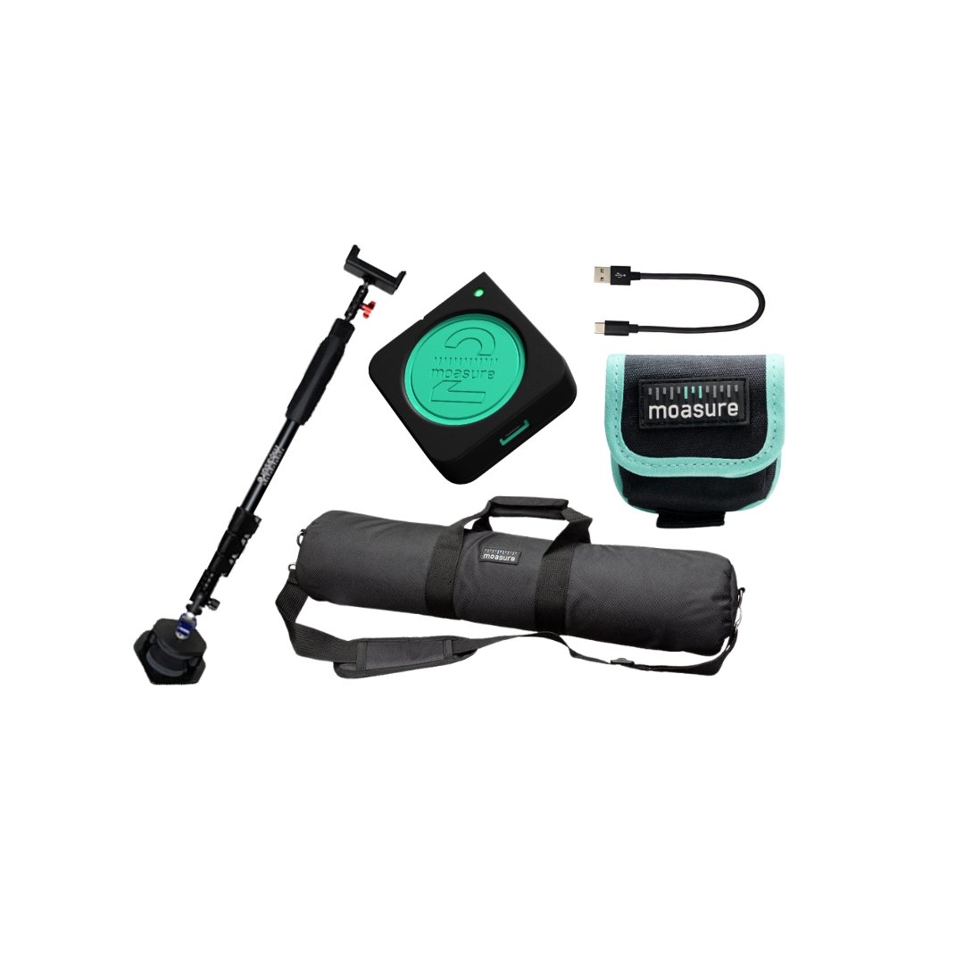
Montera och lär dig använda Moasure STICK
Din Moasure STICK består av följande komponenter:
En skumfodrad hållare för din Moasure-enhet
En expanderbar universell smartphonehållare
En universell vridbar led
Ett Justerbart handtag
En Moasure-väska
Montera den fodrad hållare:
Använd den medföljande skruven för att fästa den fodrade hållaren på den utdragbara handtaget.
Se till att hållarens spetsiga kant är vänd uppåt innan du drar åt skruven.
Fäst den universella leden:
Fäst den vridbara universella leden på toppen av den utdragbara handtaget.
Fäst smartphonehållaren:
Fäst den universella smartphonehållaren på den universella leden.
Justera vinkeln på smartphonehållaren:
Lossa skruvens ratt på kulleden genom att vrida den moturs
Vrid och justera vinkeln på smartphonehållaren efter behov.
Dra åt skruvens ratt genom att vrida den medurs för att säkra hållaren.
Montera din Moasure-enhet:
När du sätter in din enhet i Moasure STICK vadderade hölje, undvik att hålla i själva Moasure STICK för att förhindra böjning och belastning på den flexibla leden. Vänd istället STICK upp och ner och håll i höljet, så att LED-lampan är synlig när du tittar ovanifrån.
Se till att din Moasure-enhet är jämnt placerad inom höljet under insättningen.
Din Moasure STICK är nu fullt monterad och klar att användas.
Innan du börjar mäta rekommenderar vi att du informerar Moasure-appen om att du använder Moasure STICK – detta kommer att förbättra noggrannheten.
Referenspunkten för din Moasure-enhet är placerad vid botten av det skarpa hörnet. När du har informerat Moasure-appen om att du använder Moasure STICK kommer referenspunkten att justeras till spetsen av det skumfodrade höljet.
Följ dessa steg för att informera Moasure-appen om att du använder Moasure STICK:
Öppna Inställningar genom att trycka på kugghjulsikonen i det övre högra hörnet.
Tryck på Mätalternativ.
Tryck på Använd Moasure STICK-tillbehör.
Välj Ja.
För att bekvämt använda Moasure STICK rekommenderar vi att du justerar höjden så att din hand är i ungefär midjehöjd och din underarm är horisontell när du går. Håll din Moasure STICK mellan tummen och två fingrar och bibehåll ett lätt grepp.
Moasure Firmware Updater is a PC application designed to enable users to easily view and update their Moasure device's firmware and calibration. In this guide, you'll learn how to download and use it.
Download the Firmware Updater application, which is compatible with both Windows and macOS.
Open the Firmware Updater application.
Connect your device using the provided Micro USB cable.
Upon connecting your Moasure device, your device details, including the current firmware and calibration version, will be displayed. Should there be a new firmware or calibration update, you will see the option to update. Conversely, if your device is already up to date, a clear message will confirm its up-to-date status. In rare occasions, you will be informed that your firmware needs to be repaired. This is nothing to be worried about - simply click on the "Repair" button that appears in such cases to repair you firmware.
Click on the "Update" button to initiate the update for your device. It's important to keep your device connected to power, maintain a stable internet connection and keep your application open throughout the update process to ensure its successful completion.
After your device has been updated, a confirmation message will appear. If the update encounters any issues, you have the option to retry. Should the problem persist, please contact [email protected], providing your device details for assistance.
In this section, you'll learn how to change the language of the Moasure Firmware Updater.
Select the language menu located in the top header, as highlighted in the image below.
Select another language from the dropdown menu.
The interface language will update.
I den här guiden lär du dig hur du planerar och mäter trädgårdar med Moasure.
I denna videoguide får du lära dig hur du använder funktionerna Lager, Ignorera och Extrapolera hörn för att mäta en oregelbundet formad tomt med många hinder – helt utan att använda STICKEN.
Börja med att gå runt området, rensa undan föremål där det är möjligt, och identifiera lämpliga placeringspunkter. I svår terräng kan det vara enklare att använda Moasure-enheten utan STAVEN, eftersom det minskar risken för oavsiktliga stötar som kan påverka mätresultatets noggrannhet. För att använda Moasure utan STICK gå till Inställningar, tryck på Mätningsalternativ, välj Övrigt, tryck på Använd Moasure Stick Attachment och välj Nej.
För att starta en mätning, öppna Moasure-appen och tryck på +-ikonen – när den lyser rött, placera enheten vid en tydlig startpunkt. Den är Rak linje, om du inte redan ändrat detta i dina inställningar – du kan byta vägtyp nu eller vid ett paustillfälle. När LED-lampan skiftar från rött till grönt, gå vidare till nästa punkt och placera snabbt enheten, med referenspunkten riktad mot kanten. Om ett hinder hindrar dig från att placera Moasure-enheten på önskad plats, kan du pausa vid en mer tillgänglig punkt och sedan ignorera den i appen när mätningen är klar. Om vissa hörn i trädgården inte går att nå (som i videon), kan du använda verktyget efter att mätningen är avslutad – se till att fånga minst två punkter på var sida om hörnet. Avsluta mätningen vid din startpunkt. Tryck på stoppikonen, gå till Fil och välj Spara.
Du kan nu redigera din mätning i appen. Använd Ignorera för att ta bort irrelevanta punkter – tryck på punkten, tryck Redigera, bläddra till höger och välj Ignorera. Punkten tas bort som om den inte mätts. För att extrapolera ett hörn: ta bort pauspunkter med Ignorera, dra ett diagonalt linjesegment över hörnet, tryck Redigera, bläddra till höger och välj Ext. Hörn, vilket lägger till det saknade hörnet baserat på vinklarna i mätningen. När du har både omkrets och area, spara genom att skriva över befintlig fil eller skapa en ny.
För att registrera ett nytt lager, tryck på nere i högra hörnet av appen och sedan på Lägg till lager. Gå tillbaka till samma startpunkt där du började mäta trädgårdens omkrets, och registrera en andra punkt längs samma kant – appen kommer automatiskt att byta vägtyp till Ignorera linje. Ändra vägtyp för att passa nästa lager, oavsett om det är Följ linje, Båge eller Väggläge, och kom ihåg att döpa om och spara varje nytt lager.
När alla lager har mätts in och din mätningsritning är färdig, tryck på Fil, och välj önskat filformat.
I den här guiden mäter vi en trädgård som är ungefär 12 x 8 meter. Om vi planerar att stanna var sjätte meter – vilket blir ungefär var sjätte sekund – kommer vi att stanna ungefär 16 gånger.
En annan del av planeringen är att tänka igenom vilken vägtyp vi kommer att använda. Om trädgården är rektangulär kan vi använda rak linje. Om trädgården har kurvor behöver vi använda följ linje för att kunna fånga de böjda kanterna. Om trädgården har både raka och böjda kanter kan vi använda en kombination av raka och följ linjer. Vi kan ändra vägtyp både i början av mätningen och efter varje pauspunkt (den punkt där vi placerar enheten).
Slutligen behöver vi ta hänsyn till eventuella objekt i vägen, så att vi kan planera hur vi bäst undviker dem. Om vi använder rak linje kan vi gå runt ett hinder utan att vår rörelse registreras – Moasure ritar en rak linje mellan pauspunkterna. Detta är användbart vid stora hinder, eftersom vi kan välja ignorera linje under mätningen eller efteråt beroende på behov. Om vi istället använder följ linje kommer enheten att registrera exakt hur vi rört oss.
Observera att ignorerade linjer inte kan märkas upp. Om du vill märka ut var ett objekt börjar och slutar, kan du istället använda rak linje för att registrera objektets längd och sedan lägga till en etikett. Läs mer om detta i vår guide Redigera etiketter.
Vi kommer att använda mätningstypen Sluten form, eftersom vi börjar och slutar på samma plats, och eftersom vi vill få fram trädgårdens totala yta i kvadratmeter. Yta i kvadratmeter visas endast när du använder mätningstypen Sluten form. Eftersom trädgården inte har några kurvor använder vi rak linje för varje vägsektion.
Använd verktyget Ignorera för att ignorera punkter i ett mätdiagram.
Med verktyget Ignorera kan du bortse från en punkt som om den aldrig hade registrerats. När en punkt ignoreras, ritas en linje mellan punkten före och efter den ignorerade punkten. Detta är användbart när du exempelvis har registrerat en punkt för att hålla dig inom tidsgränsen för mätningen, eller när du har behövt navigera runt ett hinder.
Med appversion 3.0 eller senare kan du nu ignorera pauspunkter direkt under pågående mätning.
När din Moasure-enhet står still och en pauspunkt skapas, visas alternativen Etikett och Ignorera på arbetsytan.
Tryck på Ignorera.
Som standard gäller detta den aktuella pauspunkten – den heldragna linjen mellan föregående och nuvarande punkt i mätningen blir streckad, vilket visar att den aktuella punkten är markerad som ”tillfällig”. Punkten utesluts dock inte förrän du mäter en ny punkt.
Fortsätt mätningen till nästa pauspunkt.
När du står still och nästa pauspunkt har registrerats, kommer den ignorerade punkten att visas i grått och den streckade linjen försvinner. En heldragen mätningslinje kopplar nu samman den aktuella pauspunkten med den föregående verkliga pauspunkten och hoppar över den ignorerade punkten.
Tryck på en specifik tidigare pauspunkt.
Tryck på Ignorera.
Punkten kommer att visas i grått och ignoreras av mätdiagrammet.
Du kan även ignorera pauspunkter efter att en mätning är avslutad:
Tryck på Fil.
Tryck på Öppna.
Tryck för att välja en fil.
Välj den punkt du vill ignorera.
Om du behöver återställa en ignorerad punkt:
Tryck på den ignorerade punkten.
Tryck på Redigera.
Tryck på Ångra ignorering.
Detta ger dig flexibilitet att justera mätningen, och gör det möjligt att både ignorera och återställa punkter efter behov.
Istället för att ignorera varje punkt manuellt kan du även använda verktyget Auto Ignore. Auto Ignore ignorerar automatiskt punkter som ligger på samma linje mellan start- och slutpunkt.
Alla punkter kan inte ignoreras – om en punkt inte kan ignoreras kommer den att visas i grått i appen och går inte att trycka på.
Följande punkter kan inte ignoreras:
En startpunkt
En slutpunkt
En punkt som redan har ignorerats (en så kallad ignorerad punkt)
I den här guiden kommer du att lära dig vikten av att placera din Moasure-enhet på ett sätt som säkerställer att den är helt stilla. Du kommer även att lära dig hur du gör detta på svår terräng."
För att undvika att överbelasta sensorerna är det viktigt att sätta ner Moasure-enheten försiktigt och se till att den är helt stilla. När enheten är helt stilla fångas en punkt som inkluderar X-, Y- och Z-koordinater. LED-indikatorn på din Moasure kommer att lysa grönt för att signalera att en punkt har registrerats.
Om du mäter med din Moasure STICK kan det vara bättre att hålla den med tummen och de två första fingrarna istället för med handflatan. Att hålla din Moasure STICK med fingrarna kan göra det enklare att sätta ner enheten försiktigt.
Tänk på att sätta ner enheten försiktigt är det viktigt att vara bestämd när du placerar STICK-enheten. Undvik att sväva över punkten där du vill placera den.
Olika terränger kan ibland göra det svårt att hålla enheten helt stilla. Här är några tips för olika terrängtyper.
På ytor som gräs, bark eller konstgräs kan det vara utmanande att hålla Moasure helt stilla.
På denna typ av ojämn eller grov terräng kan du trycka STICK-enheten försiktigt ner för att hjälpa till att hålla enheten stilla så att en punkt kan registreras.
Dock kan det i vissa fall vara mer lämpligt att mäta utan att använda Moasure STICK, särskilt när du till exempel mäter genom högt gräs. Genom att mäta utan STICK får du bättre kontroll över placeringen.
På en lutande yta, som en kulle eller ramp, kan vikten av STICK-enheten ibland orsaka att Moasure rör sig något. Denna rörelse gör det svårt för enheten att registrera en punkt.
För att hålla enheten helt stilla så att den kan registrera en punkt, låt STICK-enheten vila mellan din tumme och pekfinger (format som ett V).
Håll Moasure STICK med ett lätt grepp mellan dina fingrar och tumme istället för med hela handen – detta hjälper till att förhindra okontrolerade rörelser och gör att du kan sätta ner enheten mer försiktigt.
Sätt ner enheten försiktigt och bestämt. Undvik att sväva över pauspunkten. Kom ihåg, även om det kan kännas ologiskt, ju snabbare du rör dig och sätter ner enheten, desto mer exakt blir din mätning.
Place the device down gently – avoid knocks, bangs and impacts which negatively impact Moasures sensors.
You can watch the video below for a demonstration of how to measure on different surfaces. The video also demonstrates how to master pace and rotation.
Lär dig om hur ditt tempo påverkar mätnoggrannheten.
Vid rörelsebaserad mätning ökar mätfelet exponentiellt över tid. Detta innebär att du behöver gå snabbt och rotera din enhet långsamt.
För att minimera fel och maximera mätnoggrannheten, bör du inte ta längre än 8 sekunder innan du pausar – att pausa innebär att du sätter ner din Moasure-enhet för att fånga en punkt. Oroa dig inte, detta betyder inte att du måste slutföra en hel mätning inom 8 sekunder. Du kan pausa så många gånger du behöver för att slutföra en mätning.
För att hjälpa dig att hålla dig inom tidsramen på 0 till 8 sekunder har Moasure-appen en praktisk tidslinje och ljudsignaler.
Tidslinjens sektioner - Timer
Vit: Denna del fylls på mellan 0 och 6 sekunder.
Gult: Denna del fylls på mellan 6 och 8 sekunder.
Röd: Denna del fylls från och med 8 sekunder och framåt.
Även om det kan verka oväntat, desto snabbare du rör dig, desto mer exakt blir din mätning.
Förutom de visuella indikationerna i appen i form av en tidslinje (timer), får du också ljudåterkoppling i form av ett pipande ljud. Ett långsamt tickande ljud hörs vid 6 sekunder och övergår till ett snabbare tickande vid 8 sekunder. När det långsamma tickandet börjar höras, bör du förbereda dig på att sätta ner enheten.
Oroa dig inte om du inte kan röra dig runt ett hinder inom 8 sekunder. Du kan pausa så många gånger som behövs och så länge det tar för dig att komma runt hindret.
Om du inte vill att dessa pauspunkter ska registreras i din mätning kan du ändra vägtypen till 'Ignorera linje' innan du går runt hindret.
Ett annat sätt att mäta runt hinder är att använda efter att din mätning är klar för att ta bort pauspunkter från din ritning. Varje gång du ignorerar en punkt, kommer punkterna före och efter den ignorerade punkten att kopplas samman.
Om du föredrar att titta istället för att läsa, kan du se videon nedan som går igenom alla tre aspekterna av att bemästra mättekniken.
Du kanske undrar hur du kan mäta ut placeringen av träd eller sprinklers inom ett område, till exempel flera träd på en gräsmatta. Vi går igenom detta användningsområde i den här guiden.
Det finns två sätt att göra detta. Du kan antingen göra allt i en enda mätning, eller först slutföra en mätning och därefter lägga till ett lager. Vi förklarar båda alternativen samt deras för- och nackdelar nedan, med start i alternativet med en enskild mätning.
1. Mät gräsmattans omkrets
– Börja med att mäta gräsmattans omkrets. – Gå tillbaka till startpunkten utan att avsluta mätningen.
2. Registrera trädens positioner
– Ändra vägtyp till Punktväg. Gå till det första trädet och placera enheten vid trädets position. Upprepa processen tills alla trädpositioner är registrerade. – Om du inte kan nå ett träd inom det rekommenderade tidsintervallet på 6–8 sekunder, kan du byta till ignorera väg innan du rör dig vidare till nästa träd och pausar där. – Pauserna däremellan markeras då som ignorerade punkter, så att du lättare kan urskilja trädpositionerna från övriga punkter. Du kan även ignorera punkter i efterhand.
3. Avsluta mätningen
– Avsluta mätningen när alla trädpositioner är markerade.
Mät gräsmattans omkrets – Börja med att mäta gräsmattans omkrets. – Gå tillbaka till startpunkten och avsluta mätningen.
Lägg till ett nytt lager – Lägg till ett nytt lager i mätningen genom att trycka på ikonen "Lager" nere till höger i appen och sedan på "Lägg till lager". – Du kommer att uppmanas att placera enheten vid den gemensamma startpunkten. Detta är startpunkten för det första lagret. – När du placerat enheten vid startpunkten och den ligger stilla, blir du uppmanad att röra dig längs första kanten. – Dessa två steg gör att Moasure-enheten och appen korrekt kan justera ditt nya lager i förhållande till det första. Under dessa steg befinner du dig i läget Ignorera väg, och du kommer att uppmanas att byta till en annan vägtyp när stegen är slutförda, så att appen kan börja rita upp mätningen.
Registrera trädens positioner – Ändra vägtyp till
– I appen ser du både gränsen för gräsytan och punkter som representerar trädens placering på ritningen. Om du har använt en enskild mätning visas allt på ett enda lager. Om du har använt lager, kommer de att visas på separata lager. I alla fall visas båda lagren som standard på ritningen, men du kan välja att dölja något av dem vid behov.
En fördel med att använda lager är att du kan dela upp mätningen över tid och spara framsteg mellan tillfällen. Om du gör ett misstag i det andra lagret behöver du bara mäta om det lagret, inte hela projektet.
En nackdel med lager kan vara att det krävs större noggrannhet vid start av nya lager, så att de justeras korrekt mot grundlagret. Om detta inte görs väl kan vinkeln bli fel. Du kan väga för- och nackdelarna för att avgöra vad som är bäst för ditt projekt.
– Tryck på valfri punkt, oavsett om det är på gränslagret eller punktlagret, för att visa
– Om du vill se koordinater i en PDF-export, märk punkterna innan export. Koordinater från punkter som har mätts med vägtyperna Punktväg eller Ignorera linje visas inte i PDF-exporten om de inte har märkts. Om det inte är nödvändigt att visa koordinater i PDF kan du hoppa över märkning – punkterna kommer fortfarande att synas visuellt i ritningen.
– Om du har märkt punkterna kommer deras koordinater och etiketter att visas under avsnittet "Märkta punkter" i PDF-filen.
Förenkla mätning av uppfarter
Moasure erbjuder ett exakt och effektivt sätt att mäta poolers omkrets, från standardrektangulära pooler till mer komplexa former som böjda eller fria designer. Genom att välja rätt vägtyp och tillämpa korrekt mätmetod kan du uppnå exakta och konsekventa resultat för ett brett spektrum av poolformer.
Detta tillvägagångssätt är idealiskt för pooler med raka sidor, såsom rektangulära pooler eller de med rundade hörn i romersk eller grekisk stil. Processen innefattar en kombination av raka linjer och bågformade mätningar.
In this guide, we're going to go through the measurement planning and measurement of a play area.
Playgrounds usually comprise of a fenced off perimiter for safety purposes and several play items (with their own boundary) within that perimiter. We can use to measure both the outline and the inner areas and view them relative to each other and view the square meters separately for each. We however don't have to use layers if we're only interested in one area (e.g. the outline) or if we're not interested in viewing the individual area calculations of the inner structures. We can always add more layers to a measurement afterwards. We're going to measure up the playground below. We will use Layers to capture the individual areas. It comprises of:
A Perimiter (not fenced-off).
Several elevated areas that house the toys (e.g. swing, sea-saw, locomotive)
Tryck på bakåtpilen uppe i vänstra hörnet tills du är tillbaka i arbetsytan.
Tryck på Spara.
Tryck på bakåtpilen uppe i vänstra hörnet tills du återvänder till arbetsytan.
Tryck för att växla mellan Utjämnad Z och Verklig Z:
a. Utjämnad Z (Utjämnad höjdlinje): Tryck här för att jämna ut mindre hinder som växter eller räcken och få en jämnare representation av spårningslinjen.
b. Verklig Z (Verklig höjdprofil): Tryck här för att visa ofiltrerade och exakta höjdskillnader, vilket ger en korrekt återgivning av terrängen så som den mättes.
Measure a Yard or Garden
Measure Volume
Measure Pools
Measure Playgrounds
Measure Elevation
Measure Staircases
Measure Around Obstacles
Measure Circles and Arcs
Avsluta mätningen – Avsluta mätningen när alla trädpositioner är markerade.
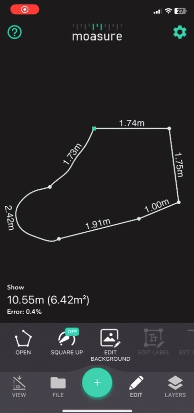
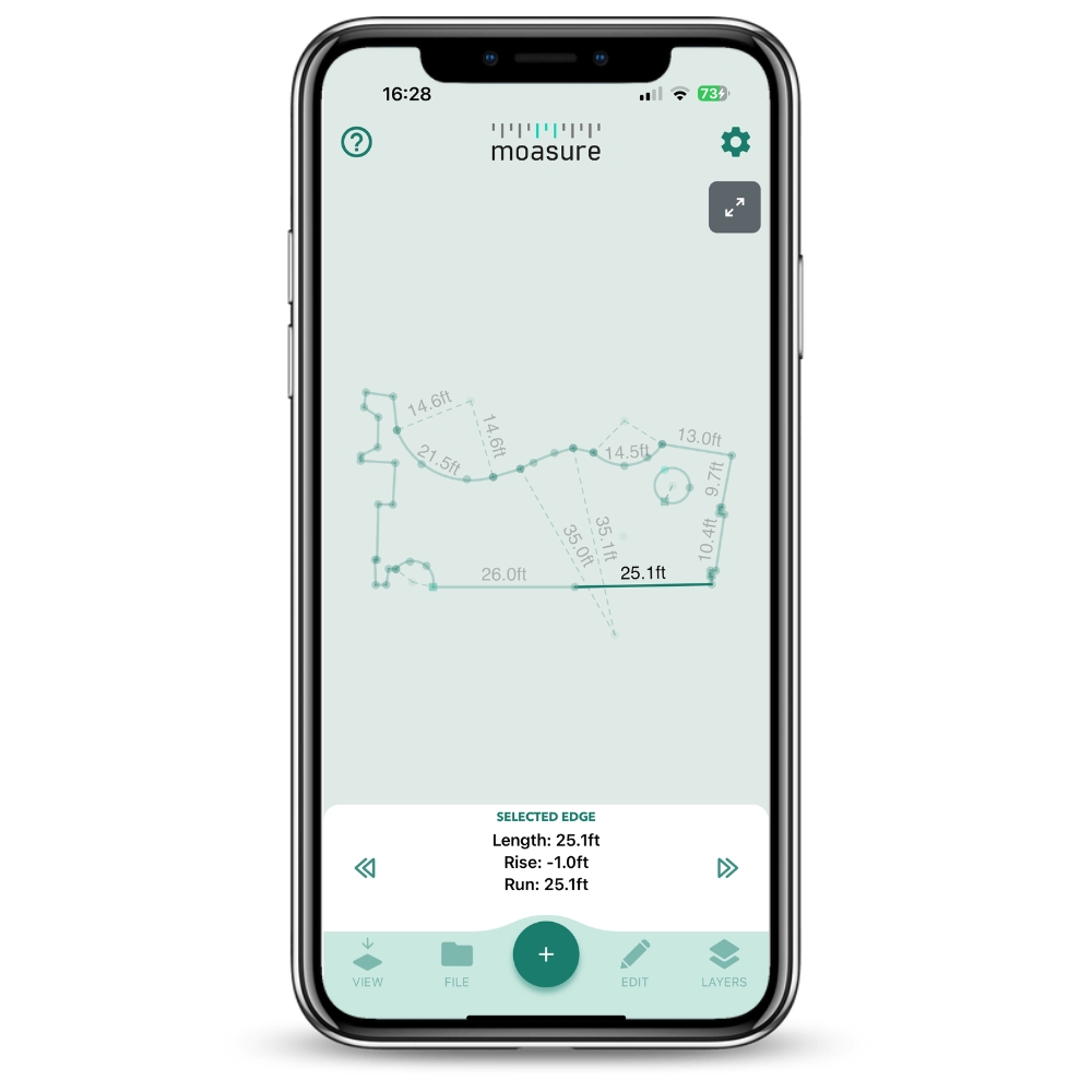

Layout Mode
±0.5%
Not Available
Om din volymmätning totalt är 100 m³, är noggrannheten inom ±1.5%, vilket resulterar i en potentiell felmarginal på upp till 1,5 m³.
If your Layout measurement totals 100m - the accuracy is within ±0.5%, resulting in a potential error of up to 0.5m.
If your Volume measurement totals 300ft³ - the accuracy is within ±1.5%, resulting in a potential error of up to 0.167yd³.
If your Layout measurement totals 300ft - the accuracy is within ±0.5%, resulting in a potential error of up to 1.5ft.
If your Volume measurement totals 100m³ - the accuracy is within ±3%, resulting in a potential error of up to 3m³.
Layout not available
If your Volume measurement totals 300ft³ - the accuracy is within ±3%, resulting in a potential error of up to 0.33yd³.
Layout not available
Omkrets
±0.5%
±1%
Nivå och höjdskillnad
±0.3%
±0.5%
Area
±1%
±2%
Volym
±1.5%
±3%
Observera att den är expanderbar för olika telefonstorlekar.
Tryck på Redigera.
Bläddra bland alternativen och tryck på Ignorera.
Punkten kommer att visas i grått och ignoreras i mätdiagrammet.
On sloped surfaces, let the STICK rest between your thumb and index finger. The weight of the STICK alone will help keep the device completely still so that it can record a point.
Välj referenslinje
Välj en lång kant av uppfarten som din referenslinje för att säkerställa korrekt placering av lager.
Den första linjemätningen kommer att användas varje gång ett nytt lager läggs till.
Välj mätningstyp
Öppna Moasure-appen.
Tryck på 'Sluten form' i listan över tillgängliga mätningstyper.
Starta omkretsmätning
Välj en minnesvärd startpunkt så att du kan avsluta mätningen på samma plats.
Börja mäta omkretsen med ‘Rak linje’ som vägtyp.
Gå snabbt längs kanten och justera referenspunkten vid slutet av Moasure STICK så att den ligger i linje med varje del av uppfarten som du vill mäta in.
Placera enheten snabbt men försiktigt.
Blanda vägtyper
Använd en kombination av vägtyper (t.ex. 'Båge') för olika delar av uppfarten.
För 'Båge' måste du fånga minst tre stoppunkter: början, mitten och slutet.
Appen ritar den bästa cirkelbågen baserat på dessa punkter.
Navigera runt hinder
Om det finns hinder, som soptunnor, navigera runt dem och fortsätt mäta.
Avsluta mätningen
Placera Moasure-enheten vid startpunkten för att avsluta.
Tryck på den röda stoppikonen i mitten av appen för att avsluta mätningen.
Spara projektet
Tryck på ‘Arkiv’ och sedan ‘Spara’ för att spara i en projektmapp.
Tryck på ikonen “Lager” nere till höger och välj ”Lägg till lager”.
Placera enheten vid delad startpunkt (startpunkten för grundlagrets mätning).
Vänta tills LED-ljuset växlar från rött till grönt för att bekräfta mätningen.
Fånga andra punkt
Fånga den andra punkten längs den ursprungliga kanten.
Den delade startpunkten måste vara densamma varje gång, men den andra punkten kan ligga något före eller efter.
Ignorera linjevägtyp
Efter att andra punkten har fångats byter appen till vägtypen "Ignorera linje".
Detta hjälper till att följa rörelser och positioner utan att rita eller registrera denna sektion.
Mät trädstammen
Byt till vägtypen "Cirkel" för att mäta trädstammen.
Fånga minst 3 punkter runt trädstammen.
Tryck på den röda stoppikonen för att avsluta, och appen ritar ut bästa passande cirkel.
Spara lagret
Observera att valet ‘Spara’ skriver över den befintliga filen.
Välj ‘Spara som kopia’ för att spara en ny fil.
Visa i 2D och 3D
Visa ritningen i 2D-vy ("planvy") för ett top-down-perspektiv.
Tryck på 3D-kuben för att se standard 3D-visualisering.
Tryck på enskilda stoppunkter för att se deras XYZ-koordinater.
Ytnätsvy (Surface Mesh View)
Tryck på 3D-ytikonen för att visa ytnätet, representerat av en färgskala från blått (lägsta punkt) till rött (högsta punkt).
Tvärsnittsverktyg (Cross Section Tool)
Använd verktyget för att mäta avståndet mellan två punkter.
Välj en baspunkt, tryck på ‘Visa’ > ‘Tvärsnitt’, och välj en andra punkt.
Exportalternativ
Tryck på Arkiv > Exportera för att se tillgängliga format, inklusive CAD (DWG och DXF) samt PDF.
Denna handledning täcker de viktigaste stegen för att mäta en uppfart med hjälp av Moasures lagerfunktion samt hur du granskar och exporterar den insamlade informationen. Genom att följa denna guide kan du noggrant mäta och dokumentera uppfarter och andra områden med komplexa former.
Välj mätningstypen "Sluten form" I Moasure-appen, tryck på +-ikonen och välj Sluten form för att börja.
Starta enheten För att slå på enheten, håll Moasure-enheten vertikalt och rotera den försiktigt 180° fram och tillbaka tills LED-lampan blinkar blått och sedan rött.
Starta från en tydlig referenspunkt Placera enheten vid en definierad punkt längs poolkanten, justera referenspunkten noggrant för jämna och pålitliga resultat.
Rak linje-vägtyp Börja gå längs poolens raka sidor med vägtypen
Gå i jämn takt.
Pausa halvvägs längs långa sträckor för att dela upp linjen i kortare, mer exakta segment.
Mät bågformade hörn När du närmar dig rundade hörn, byt till vägtypen Båge.
Placera enheten på tre punkter: början, mitten och slutet av kurvan.
Moasure genererar automatiskt en bäst-passande båge.
Navigera runt hinder Använd vägtypen Rak linje för att gå runt räcken eller andra hinder utan att påverka noggrannheten. Denna vägtyp mäter det raka avståndet mellan två punkter, oavsett väg du tar – du behöver alltså inte fri sikt. Moasure registrerar ändå en rak mätning från punkt A till B.
Avsluta mätningen Avsluta vid din ursprungliga startpunkt och tryck på den röda stoppikonen för att stänga formen.
Appen visar omedelbart omkrets och yta.
Ett på 1 % eller mindre anses vara ett korrekt mätresultat.
Detta tillvägagångssätt är bäst lämpat för pooler med njurform, cirkulära designer eller varierande kantkonturer. Moasures flexibla vägtyper gör det möjligt att noggrant följa kurvor och navigera runt hinder.
Planera innan du börjar Ta en stund för att granska poolens form, identifiera hinder och avgöra vilka vägtyper som krävs.
Börja med Båge eller Spårningslinje
Använd vägtypen Båge när du mäter tydliga kurvor eller när hinder (t.ex. räcken) förhindrar en direkt spårning.
Använd vägtypen Spårningslinje för att följa kontinuerliga eller oregelbundna kurvade kanter och pausa var 6–8:e sekund.
Navigera runt hinder med vägbyte
Använd Rak linje för att gå runt hinder samtidigt som du fortfarande registrerar linjärt avstånd.
Bibehåll god teknik
Gå snabbt och undvik plötsliga eller ryckiga rörelser.
Pausa när tidsmätaren är i det gröna området för bästa resultat.
Försök pausa vid logiska punkter, som riktändringar eller naturliga avbrott i poolens form.
Stäng och spara mätningen
Återvänd till din startpunkt och tryck på den röda stoppikonen för att avsluta.
Appen beräknar automatiskt yta och omkrets.
Some pathways.
We're going to start by measuring the separate structures that house the toys. We will use Closed Shape as the Measurement Type and Straight Line as the Path Type as the areas don't have curvatures. With Layers, we have to remember the first 2 points of our initial measurement layer (the Base Layer). When we add a new layer, we have to go back to the start of the first point of the Base Layer and then to the second point of the Base Layer before we start measuring our Second Layer. This is required to correctly orient the measurement layers in relation to each other. Once we have captured the two reference points, we can walk to the start of our Second Layer (this will automatically be set to Ignore Line so that the path is not actually captured). The app will prompt you to go to the start and second point of the base layer each time you start a new layer measurement. It's recommended to place something in/on the ground to remember the two points.
Once the structures are measured, we're going to measure the perimiter in both Trace Line and Straight Line.
Download for Windows
Download for macOS


I den här guiden lär du dig hur du mäter volymen och 3D-terrängen på en plats.
Din Moasure-enhet är som standard utformad för att mäta höjd, och alla mätningar sker i 3D. Från och med appversion 2.0 introducerar Moasure-appen beräkningar av volym och yta, vilket förbättrar dina möjligheter.
Om du föredrar att titta istället för att läsa kan du se instruktionsvideon nedan:
För att mäta volym noggrant, följ dessa steg:
Mät omkretsen.
Gå tillbaka till startpunkten utan att avsluta mätningen.
Ändra till Punkter.
Mät punkter inom omkretsen. Ju fler punkter du fångar, desto bättre blir ytanpassningen och noggrannheten. Fånga extra punkter i områden med höjdvariationer eller ojämnheter.
När du är nöjd med de insamlade punkterna, gå tillbaka till den ursprungliga startpunkten (detta förbättrar noggrannheten).
Slutligen,
Moasure stöder att fånga volym som ett extra lager, vilket gör att du kan återvända till en plats senare och mäta volym baserat på en tidigare inspelad omkrets.
Detta är särskilt användbart för landskapsarbete, schaktning eller gräsmatteprojekt där höjdinformation kanske inte behövs under det första platsbesöket men kan läggas till senare.
Säkerställ att din ursprungliga mätning inkluderar en tydlig, rak A–B referenslinje.
Vi rekommenderar att markera Punkt A och Punkt B med synliga markörer (t.ex. flaggor eller koner) för att göra det enklare att återvända till dessa positioner när du lägger till ett nytt lager.
Öppna din sparade mätning och tryck på Lager-ikonen.
Tryck på Lägg till lager.
Gå tillbaka till Punkt A (startpunkten) och gå till Punkt B för att återspåra din A–B referenslinje.
En svart linje kommer att visas för att bekräfta justeringen.
För att visa mätresultaten, följ dessa steg:
För att se ett ytnät av det uppmätta området, tryck på Ytikon.
Under ytnätet hittar du beräkningen av ytarea och volym.
För att visa en höjdkarta, tryck på Konturikonen. Höjdkartor används för att representera topografi eller höjdvariationer inom ett visst område. De visar vanligtvis linjer, kallade höjdkurvor, som förbinder punkter med samma höjd. Dessa linjer hjälper till att visualisera markens form och identifiera höjdskillnader. Avståndet mellan höjdkurvorna indikerar lutningens branthet – ju närmare linjerna ligger varandra, desto brantare är lutningen, och vice versa. Höjdkurvornas intervall ställs in automatiskt av Moasure-appen.
För avancerade beräkningar, såsom schakt- och fyllvärden eller tillägg av material till en plats, kan du använda verktygen och .
Verktyget är särskilt utformat för att beräkna volymen av ett material (såsom täckbark, jord eller grus) baserat på en given yta och önskat täckdjup. Genom att multiplicera dessa värden beräknas den totala volymen som krävs.
Verktyget används för att fastställa mängden material som måste schaktas bort eller fyllas på vid markarbeten eller byggprojekt för att uppnå önskade nivåer och/eller utjämna en plats.
Använd verktyget när du behöver beräkna volymen för ojämn, kuperad och/eller sluttande mark eller räkna ut volymen av ett specifikt material (som täckbark, jord eller grus) som krävs för att täcka en viss yta till ett önskat djup. Detta är användbart för trädgårdsmästare eller landskapsarkitekter som planerar att applicera täckmaterial. Det är också användbart för markanläggare som förbereder grundläggning eller baslager för gångvägar eller uteplatser. Låt oss säga att en trädgårdsanläggare vill veta hur mycket täckbark som behövs för att täcka en yta till ett djup av 15 cm (~6 tum), eller att en markanläggare vill skapa ett hårt packat underlag till ett djup av 15 cm för att lägga plattor eller betong. De kan då enkelt beräkna materialvolymen genom att multiplicera ytan med 15 cm. Verktyget Lägg till Djup förenklar detta genom att förberäkna ytan och erbjuda verktyg (såsom ett reglage) för att specificera djupet, vilket resulterar i en volymberäkning.
I slutändan beror valet av verktyg på det specifika projektet.
Din första mätning
Lär dig hur du mäter area, omkrets och hanterar kurvor och hinder med hjälp av din Moasure-enhet.
Rensa bort hinder: Ta bort eventuella föremål från viktiga placeringspunkter.
Välj en startpunkt: Välj en lättidentifierad plats (t.ex. ett hörn) för att starta och avsluta din mätning.
Öppna Moasure-appen och tryck på +-ikonen för att starta en ny mätning.
Välj som mätningstyp.
Slå på enheten:
Håll Moasure-enheten/STICKEN vertikalt.
a.
Gå snabbt och pausa för att registrera punkter.
Placera enheten när indikatorn är i grönt läge eller senast i gult läge på tidslinjen för bästa noggrannhet.
b.
Använd Följ linje för att mäta böjda kanter.
Gå jämnt längs kurvan medan Moasure registrerar banan.
Appen förblir i "Följ linje"-läge tills du byter.
c.
Använd Båge när du inte kan följa kurvan direkt, t.ex. vid växtlighet eller andra hinder.
Registrera tre punkter: början, mittpunkten och slutet av bågen.
Appen visar en bäst-passande båge när du är klar.
Dela upp sträckor i ungefär lika segment för bättre noggrannhet.
Placera STAVEN:
Håll den stadigt med lätt grepp och placera snabbt men försiktigt.
Stöd handen mot marken (gräs/löv) för stabilitet.
Avsluta vid din startpunkt.
Tryck på Stopp-ikonen för att avsluta mätningen.
Spara ditt arbete:
Tryck på Fil, skapa en projektmapp, namnge filen och spara.
Öva några mätningar innan du använder Moasure i riktiga projekt.
Använd pauspunkter för att planera nästa vägtyp.
Håll ett jämnt, snabbt tempo och ett lätt grepp för bästa resultat.
Lär dig hur du sätter på och stänger av din enhet.
Sätt på din Moasure-enhet genom att hålla den vertikalt och rotera den försiktigt 180° fram och tillbaka 2–3 gånger.
LED-indikatorn börjar blinka blått när enheten är på.
För att slå på din Moasure-enhet med hjälp av dubbeltrycksmetoden, följ dessa steg:
Placera din enhet i din hand.
Använd ditt fingertopp för att dubbeltrycka på enhetens framsida för att slå på den.
If you would like to change your Moasure double-tap sensitivity, please follow these steps:
Go to Settings within the Moasure app (tap the cog in the top-right corner of the app)
Go to Account & Device Management and tap on Select Device
Tap the Information icon for your listed device
When using Moasure STICK, you can turn on Moasure without removing the device from the foam-lined housing:
Place the STICK down on a solid, flat surface
Double tap the sharp edge of Moasure (where the LED indicator is located)
By default, your Moasure device automatically switches itself off after 30 seconds of inactivity. However, you can adjust the device's disconnection time by following these steps:
Go to Settings within the Moasure app (tap the cog in the top-right corner of the app)
Tap on Measuring Options
Scroll down until you see Moasure Device Disconnection where you will be able to set how long you would like the Moasure device to stay awake. You can choose from 30 seconds, 1 minute, 2 minutes and 5 minutes
The rotate-to-turn-on feature is available on firmware versions from v1.28 upwards – if your firmware version is v1.28 or newer but your device is set to the Double-Tap method, you can change to the Rotate method in the app by following these steps:
1. Go to Settings within the Moasure app (tap the cog in the top-right corner of the app)
2. Tap on Account & Device Management
3. Tap on Device Preferences under Device Management
4. Tap on Firmware
5. Turn on your Moasure device. The device needs to be turned on in order to make changes. Once the device is connected, you will see the device data appear on the app screen
6. Tap on your current Turn on method and change it to your preferred turn on method by toggling between the two options to suit your preference.
Moasure är ett kraftfullt verktyg för att mäta golfbanor, inklusive fairways, greener, gångvägar och bunkrar. Med hjälp av rörelsebaserad teknik fångar det upp exakta avstånd, höjder och volymer, vilket gör komplexa mätningar enkla och effektiva. Denna guide beskriver de viktigaste stegen för att mäta en golfbana på ett effektivt sätt.
Ställ in Moasure på din föredragna enhet (meter eller tum) i appens inställningar.
Välj en lättillgänglig startpunkt och markera den som Punkt A, med Punkt B på tillräckligt avstånd för att säkerställa noggrannhet.
Använd markörer (t.ex. golfbollar eller flaggor) för att enkelt identifiera punkterna.
Starta mätningen:
Börja vid Punkt A och gå i rask takt till Punkt B.
Håll ett jämnt tempo och se till att mätstickan glider smidigt genom luften utan att svinga eller rycka innan du placerar den snabbt men försiktigt.
Navigera i terräng:
Varje nytt börjar vid Punkt A och följer samma mätprinciper.
Lager kan inkludera ytterligare banfunktioner som bunkrar, greener eller gångvägar.
Spara framstegen efter varje lager för att undvika dataförlust.
Slingrande gångvägar: Gå med jämn takt och pausa var 6–8:e sekund för att samla in exakt höjdinformation.
Bunkrar & volymmätningar: Använd vägtypen Spårningslinje för att fånga omkretsen. För att mäta volym: Använd vägtypen P och gå i sicksack för rektangulära ytor eller i spiral för ovala former.
Använd för att visualisera höjdförändringar.
Tryck på en punkt för att se dess X-, Y- och Z-värden, samt på valda linjer för att se längd, höjdskillnad och lutning.
Tryck på Redigera > Redigera bakgrund > Lägg till bild för att lägga över en flygbild.
Justera storlek, rotation och genomskinlighet efter behov.
Gå till verktyget för att uppskatta materialvolymer vid utgrävning eller fyllning.
Justera djupreglaget för att beräkna exakt schakt-, fyllnads- och nettovolym.
När alla mätningar är slutförda, tryck på Arkiv > för att spara i format som PDF, DWG, DXF eller MFiles.
Dela data enkelt via e-post eller med andra Moasure-användare.
Med Moasure blir det enkelt och effektivt att samla in noggranna mätdata för komplexa former som bunkrar, greener och slingrande gångvägar på golfbanor. Det sparar tid samtidigt som du får tillförlitlig data för dina projekt.
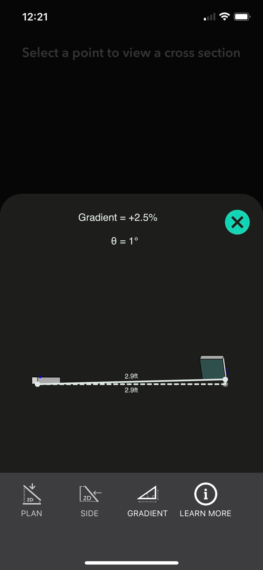
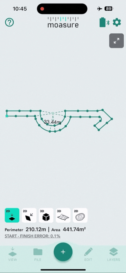
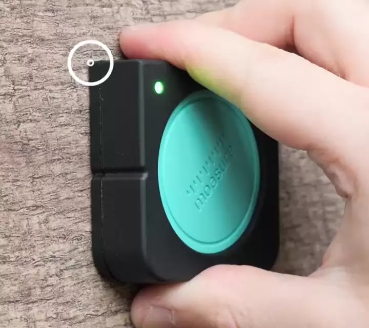
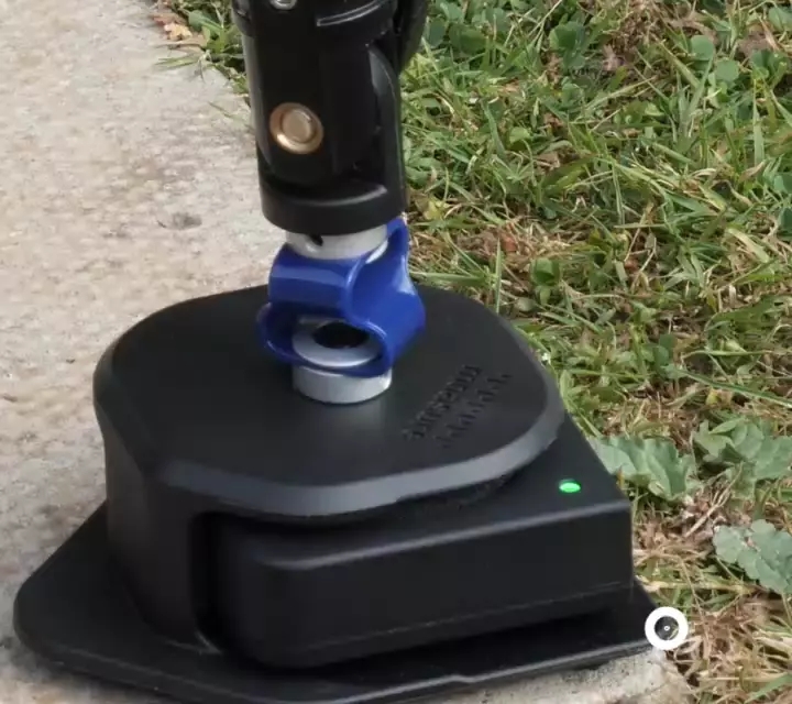


Den här inställningen låter dig justera teckenstorleken på måttangivelser i appen. Obs: detta påverkar inte teckenstorleken för annan text i appen.
För att ändra inställningen, följ stegen nedan:
Öppna Inställningar genom att trycka på kugghjulsikonen uppe i högra hörnet.
Tryck på Visningsalternativ.
Tryck på Teckenstorlek för mått under Inställningar för skärmen. Välj önskad teckenstorlek.
.
Moasure växlar automatiskt till "Ignorera linje"-läge, vilket låter dig gå fritt till det område där du vill börja samla in höjddata.
Gå till din valda startpunkt inne i omkretsen (vi rekommenderar att markera denna som Punkt C).
Ändra din vägtyp till Punkter.
Börja samla in höjddata genom att gå i ett spiral- eller sicksackmönster inom det avgränsade området.
Samla fler punkter i områden med sluttningar eller ojämn terräng.
Gå tillbaka till Punkt C för att fånga din slutpunkt.
Tryck på den röda stoppikonen för att avsluta lagret.
Använd verktyget Schakt/Fyll när du är involverad i mark- eller byggprojekt som kräver att terrängen jämnas ut. Det här verktyget hjälper till att bestämma mängden material som måste schaktas bort eller fyllas på för att uppnå de önskade nivåerna. Låt oss säga att en trädgårdsanläggare arbetar med att skapa en terrasserad trädgård på sluttande mark. De kan använda schakt- och fylltekniker för att genomföra detta. Vid schaktfasen kan anläggaren gräva bort högre delar av sluttningen för att skapa en plan yta för trädgårdsterrasser. Anta att de tar bort 100 kubikmeter jord under denna process. Därefter, i fyllfasen, kan de tillföra ytterligare jord eller fyllnadsmaterial för att höja de lägre delarna av sluttningen och fylla ut utrymmena mellan terrasserna. Anta att de lägger till 100 kubikmeter fyllnadsmaterial. I detta scenario kommer schakt- och fyllvärdena vara lika, vilket resulterar i en nettovolym på 0. Det innebär att mängden borttagen jord (schakt) balanseras av mängden tillförd jord (fyll). Detta hjälper till att skapa en plan yta i den terrasserade trädgården samtidigt som en jämn volymbalans bibehålls.


Rotera den försiktigt fram och tillbaka 180 grader tills LED-lampan blinkar blått.
Placera enheten vid startpunkten:
Rikta in referenspunkten mot hörnet.
LED-lampan ändras från röd till grön som bekräftelse på att första punkten har registrerats.
Växla mellan vägtyper efter behov (rak linje, följ linje, båge etc.).
Fortsätt rikta in STICKENS referenspunkt mot kanten av banan.
Visa resultat:
Omkrets och Area visas automatiskt.
Ändra enheter: Tryck på kugghjulet, välj Mätenheter och välj mellan metriskt eller imperial.
Exportera mätningen:
Tryck på Fil > Exportera, och välj ett format som PDF, DWG eller DXF.
Tap on Double-Tap Sensitivity and choose between the following settings; Low (harder tap), Medium, High (softer tap)
Gå smidigt runt hörn.
Håll enheten stilla på ojämnt underlag för att fånga en pauspunkt.
Slutför omkretsen:
Fortsätt mäta tills hela gränsen är registrerad.
Tryck på den röda Stopp-ikonen för att spara.
Välj en punkt, tryck på Redigera > Redigera etikett och ge den ett namn för enkel referens.
Med lager kan du fånga flera områden inom en och samma mätning. Det ger dig en komplett, måttsatt ritning där alla former är placerade i förhållande till varandra.
Möjligheten att fånga flera områden eller former inom en enda mätning möjliggörs genom att definiera den första kanten. Denna initiala kant fungerar som en referens- eller datumlinje, vilket säkerställer korrekt placering av efterföljande former som en del av den totala mätningen.
Beakta dessa tre viktiga faktorer när du väljer din första kant:
Längd: Ju längre den första kanten är, desto mindre påverkan kommer mänskliga fel att ha
på mätningen, så gå i rask takt och sikta på att pausa precis när
timerfältet övergår från den gröna zonen till den gula zonen. Behåll
en jämn, stadig gång när du går – detta kommer att förbättra Moasures noggrannhet i
positionering av varje lager relativt de andra.
Tydlighet och repeterbarhet: Välj en tydlig och lätt repeterbar första kanten. För optimal klarhet och enkelhet rekommenderar vi att du väljer en lång rak linje med hjälp av vägtypen 'Rak Linje' för tydlighet.
Plats: Placera din första kant centralt inom ditt totala mätområde. Detta minskar avståndet du behöver förflytta dig för varje ytterligare lager.
När du fångar efterföljande lager, återgå till den första kanten så att Moasure kan fastställa den relativa placeringen av det nya lagret. Att hålla den första kanten centralt placerad maximerar noggrannheten genom att minimera förflyttningsavståndet mellan olika områden.
För att starta en mätning, tryck på '+' ikonen i mitten längst ner på skärmen;
Välj 'Sluten Form' från listan med tillgängliga mätalternativ;
Välj den 'Vägtyp' du vill använda för att starta din mätning. Vi rekommenderar 'Rak Linje' som din referenslinje (kom ihåg att du kan växla mellan andra Vägtyper under din mätning vid varje pauspunkt);
Viktigt: De två första punkterna du fångade i början av din mätning kommer att användas som 'Referenspunkter' för alla Lager. Detta säkerställer att de överlappar på rätt plats.
Viktigt: Kom ihåg att spara dina mätningar genom att trycka på Arkiv > Spara för att spara lagermätningen. Observera att Spara endast sparar den aktuella filen.
Spara som kopia är till för när du vill behålla originalmätningen oförändrad och spara din nya mätning (som nu inkluderar ditt bas-mätningslager och ytterligare lager) som en separat fil.
Se till att de två referenspunkterna är lätta att komma åt och lokalisera, eftersom varje gång du skapar ett nytt 'Lager' behöver du gå tillbaka till de två första referenspunkterna.
Idealiskt sett ska de två referenspunkterna vara åtskilda med 4-5 meter.
När du startar ett nytt lager kommer du att märka att Vägtypen automatiskt är inställd på 'Ignorera Linje'. Detta kommer att förhindra att orienteringslinjen visas på ditt mätdiagram.
När du har flyttat från referenslinjen till den första punkten i din nästa mätning och är redo att mäta, glöm inte att byta från 'Ignorera Linje' till den Vägtyp du vill använda härnäst (Rak Linje, Spårnings- Linje, Båge, Cirkel, etc.)
När du är redo att avsluta din andra mätning, tryck på den röda 'STOPP'-ikonen i mitten längst ned på skärmen.
För att lägga till nya Lager, se Punkt 6.
Alla Lager måste dela samma två första referenspunkter för att säkerställa att de överlappar på rätt plats.
När du lägger till ett nytt underlager kommer Väg mellan orienteringslinjen och den första punkten i underlagret att vara inställd på 'Ignorera Linje', vilket betyder att denna linje inte kommer att visas på ditt mätdiagram.
När du har anlänt till underlagret och när du är redo att börja mäta, ändra Vägtypen för mätningen.
Du kan växla mellan andra Vägtyper under din mätning vid valfri pauspunkt.
Moasure stöder mätning av både slutna och öppna former när du arbetar med lager. Men hur formerna hanteras beror på den form du börjar med på baslagret:
Om du börjar med en sluten form på baslagret, kommer alla efterföljande lager också att behandlas som slutna former.
Om du istället börjar med en öppen form på baslagret, kommer efterföljande lager att följa samma mönster och behandlas som öppna former.
Om du mäter en öppen form (det vill säga att du inte avslutar vid samma startpunkt), kommer Moasure automatiskt att ansluta ändpunkterna med en streckad linje för att "sluta" formen – såvida inte formen endast består av två punkter som bildar en enkel linje. Du har möjlighet att öppna upp formen igen i efterhand om det behövs. Det är viktigt att känna till dessa beteenden för att säkerställa att dina mätningar blir korrekta och uppfyller dina avsikter, särskilt när du använder Moasures lagerfunktion.
Ytberäknaren förenklar och påskyndar processen att beräkna nettot mellan flera lager. Denna funktion är särskilt användbar när du behöver fastställa ytan mellan lager – till exempel vid beräkning av landskapsytor minus planteringsytor, lekplatsytor exklusive gångvägar, eller när du drar av en poolyta från en altanyta – vilket ger värdet av den mellanliggande ytan.
Öppna Ytberäknaren
Tryck på Lager för att visa en lista över mätningens lager.
Tryck på Ytberäknare högst upp på skärmen.
Visa lagerareor
Ytan visas under lagrets namn.
Nettoarean mellan lagren visas längst ner på skärme
Dra bort lager från beräkningen
Använd fingret eller tummen för att trycka på ett lager och dra det till sektionen Bortdragna lager.
Alternativt kan du trycka på nedåtpilen bredvid det lager du vill dra bort.
Nettoarean uppdateras automatiskt när lager flyttas.
Lägg till lager igen i beräkningen
Använd fingret eller tummen för att dra ett lager från sektionen Bortdragna lager tillbaka till Tillagda lager.
Alternativt kan du trycka på uppåtpilen för att flytta ett lager från Bortdragna lager tillbaka till Tillagda lager.
Växla lagers inkludering
För att helt dölja ett lager från beräkningen, tryck på öga-ikonen för att växla dess synlighet av eller på.
Detta verktyg är användbart i en rad olika sammanhang, till exempel:
Trädgårdsanläggare som beräknar den totala gräsmatteytan minus rabatter och planteringsytor.
Pooldesigners som drar bort poolens yta från ett trädäck för att få fram den återstående ytan.
Lekplatsdesigners som fastställer den totala lekytan minus sammanlänkande asfalterade gångar.
Moasure stöder att lägga till vilket gör att du kan återvända till en plats senare och mäta volym baserat på en tidigare uppmätt omkrets. Detta är särskilt användbart för landskapsprojekt, gräsmattor eller grävningsarbeten där du först mäter ytan och sedan volymen vid ett senare tillfälle.
Säkerställ att din ursprungliga mätning innehåller en tydlig, rak A–B referenslinje.
Markera punkt A och punkt B med synliga markörer (t.ex. flaggor eller koner) så att du enkelt kan återvända till dem för justering.
Öppna din sparade mätning och tryck på Lager-ikonen.
Tryck på lägg till lager.
Gå tillbaka till Punkt A och sedan till Punkt B för att spåra referenslinjen – leta efter den svarta linjen på skärmen.
Moasure växlar till Ignorera linje-läge, vilket gör att du kan gå fritt tillbaka till din startpunkt inne i omkretsen (markera detta som
Tryck på 3D ytnät vy för att se volymberäkningar.
Välj mellan:
Lägsta punkt – använder den lägsta höjden som bas (perfekt för hål och grävningar).
Omkrets – använder ytterkantens höjd som bas (idealisk för upplag eller upphöjda ytor).
För att komma åt fler verktyg, tryck på Redigera och välj sedan:
Schakt och fyll– uppskatta hur mycket material som behöver läggas till eller tas bort för att jämna ut ytan.
Lägg till fast djup – beräkna volym under ytan – perfekt för planering av schaktning.
Applicera färger på lager och mappar med hjälp av en färgväljare, hexkod eller en förinställd palett. Att färglägga lager är idealiskt för att definiera nyckelområden i din mätning, vilket hjälper dig att visualisera utrymmen och anpassa dina mätningar till ditt varumärke.
Så ändrar du färg på lager:
Tryck på Lager för att visa en lista över mätningens lager.
Tryck på Lager-ikonen till vänster om lagernamnet – eller tryck på de tre horisontella prickarna ovanför ögonikonen – och välj sedan en färg:
Du kan välja från ett rutnät med förinställda alternativ, ange en hexkod eller använda skalan och färgväljaren.
I den här guiden får du lära dig hur du navigerar och visar mätningar i Moasure-appen. Vi kommer att gå igenom olika visningsalternativ och verktyg för att hjälpa dig att visualisera din data effektiv
När du har slutfört ett mätdiagram visas varje mätväg som registrerats mellan pauspunkter. Dubbeltryck var som helst på skärmen för att visa hela diagrammet. Dra med ett finger för att flytta mätningen, nyp med två fingrar för att zooma in eller ut, och svep med ett finger för att panorera åt vänster eller höger. Dessa navigeringsrörelser gör det enkelt att granska, justera och analysera din mätning i detalj.
2D "planvy" ger ett ovanifrånperspektiv av din mätning. Genom att trycka på enskilda paus-punkter visas deras relativa XYZ-koordinater, inklusive höjd. Tryck bort från valfri paus-punkt på skärmen för att se vyikonerna igen.
För att visualisera en mätning främst på ett sluttande plan, snarare än ett horisontellt, växla till vyn "2D ANPASSA". Detta perspektiv visar mätningen från en vinkel vinkelrätt mot det sluttande planet, vilket gör att dimensioner och areavärdet justeras därefter. Det är viktigt att notera att vid mätning på ett horisontellt plan kommer byte till "2D ANPASSA" inte att resultera i någon signifikant förändring i vyn.
För att utforska mätningar i tre dimensioner, såsom höjdskillnader eller lutningar, tryck på 3D-kubikonen. Detta växlar till 3D-vyn, där du kan nypa med två fingrar för att zooma och använda ett finger för att panorera din ritning både horisontellt och vertikalt..
Genom att trycka på ikonen för 3D-yta får du tillgång till en ytnätsvy som visualiserar höjdvariationer med hjälp av en färgskala, där blått representerar den lägsta punkten och rött den högsta. Denna vy ger en tydlig tredimensionell bild av det uppmätta området och är särskilt användbar vid analys av lutningar, terrängvariationer och nivåskillnader. Samtidigt presenteras information om yta, vilket är summan av alla ytor i 3D-modellen, samt volym, som beräknas genom att projicera den lägsta punktens höjd (det lägsta Z-värdet) mot ett horisontellt plan.
Detta gör det möjligt att snabbt bedöma både markförhållanden och massberäkningar inom området. Det finns två sätt att beräkna volym i denna vy, vilket beskrivs mer ingående på sidan Mät volym och 3D-terräng under avsnittet Förstå omkrets och lägsta punktens plan. Denna vy kombinerar tydlig visuell analys med exakta tekniska data och är ett ovärderligt verktyg för exempelvis entreprenörer, markplanerare och anläggningstekniker.
Om du har använt mätvägstypen Punktväg för att samla in höjdinformation, växla till Konturvy för att se en konturkarta över din ritning. Konturlinjerna representerar lutningens branthet: tätare linjer innebär brantare lutning, medan glesare linjer visar flackare sluttningar. Appen ställer automatiskt in konturintervallet utifrån höjdvariationerna i din mätning. Använd denna vy för att få insikt i topografin inom det uppmätta området.
Inifrån Konturvyn kan du växla mellan 2D- och 3D-vy via reglaget högst upp i arbetsytan för att bättre visualisera dina data:
2D-vy: visar konturerna i ett plant plan, vilket gör det lättare att tolka den övergripande lutningen. 3D-vy: tillför djup, och visar höjdskillnaderna i tre dimensioner för en mer realistisk återgivning.
Växla mellan vyerna för att se din mätning ur olika perspektiv och på så vis bedöma terrängen mer effektivt.
Du ändra från 2D- och 3D-konturvy samt anpassa höjdkurvor för mer flexibel visualisering av höjdskillnader, med mindre och större höjdkurvor.Mmindre höjdkurvor är tunna och utan etiketter, medan större höjdkurvor är tjocka och försedda med etiketter.
Anpassade höjdkurvor låter dig granska subtila terrängförändringar i mer detalj eller förenkla vyn för att framhäva större höjdskillnader.
Så här ändrar du höjdkurvor:
Tryck på Konturvy i en öppen mätning.
Tryck på kugghjulsikonen längst upp i vyn, till höger om växlingen mellan 2D/3D.
Överlägget Redigera höjdkurvsinställningar visas längst ner på skärmen.
Växla mellan fot och meter efter behov.
Höjdkurvsinställningarna låter dig styra hur höjdkurvor visas.
Mindre höjdkurvsintervall
Anger avståndet mellan mindre höjdkurvor.
Mindre höjdkurvor är tunna och utan etiketter.
Exempel: Om inställt på 0,5 m (50 cm) visas mindre höjdkurvor var 0,5 meter.
Större höjdkurvsintervall (Multiplikator)
Anger hur ofta större höjdkurvor ritas, baserat på en multipel av det mindre intervallet.
Större höjdkurvor är tjockare och försedda med etiketter.
Exempel:
Om det mindre höjdkurvsintervallet är 0,5 m och det större höjdkurvsintervallet är satt till 3 → större höjdkurvor visas var 1,5 m
När du har justerat värdena trycker du på Spara för att uppdatera höjdkurvorna.
Byt tillbaka till standardvy i 2D eller 3D för att interagera med enskilda element; genom att trycka på en mätlinje visas dess längd, höjdskillnad och horisontella sträcka. Om du väljer en punkt visas dess vinkel och XYZ-koordinater. Tryck utanför den valda punkten eller kanten för att återställa vyikonerna.
Växla tillbaka till den vanliga 2D- eller 3D-vyn för att interagera med enskilda element; när du trycker på en mätlinje visas dess längd, höjdskillnad (rise) och horisontella sträcka (run). Om du markerar en punkt får du upp dess vinkel samt XYZ-koordinater. Tryck någonstans utanför en vald punkt eller linje för att åter visa visningsikonerna.
Tvärsnitt låter dig mäta höjdskillnad, horisontell sträcka och lutning mellan två punkter. Så här använder du tvärsnittsfunktionen:
Tryck på en mätpunkt för att markera den.
Tryck på ”Tvärsnitt”.
Tryck på en andra punkt. Du ser då längd, höjdskillnad, horisontell sträcka, vinkel och lutning.
Tryck på ”Tvärsnitt” längst ner. Du ser då höjdskillnad, horisontell sträcka, vinkel och lutning.
Moasure fungerar genom att ansluta till den medföljande Moasure-appen och använda Bluetooth för att överföra mätdata från din Moasure-enhet till din smartphone eller surfplatta.
Ladda ner Moasure-appen (tidigare känd som Moasure PRO-appen) för din Apple/iOS-enhet.)
Moasure-appen för din Android-enhet.
A step by step guide on how to import Moasure data into Uvision.
Moasure’s measurement data can be imported into Uvision using Moasure’s CSV exports in conjunction with Uvision’s Terrain Elevation Import Wizard. This wizard enables mapping Moasure’s format with Uvision’s. Here's a step-by-step guide:
Export the Data from Moasure:
Open the measurement you want to import using the Moasure app.
Tap "File" > "Export," then select "CSV."
Configure the export settings by choosing what data to include. For a simpler import, switch off all toggles except “Include Column Heading.”
2. Open the Import Wizard in Uvision:
Open Uvision, go to the "Tools" menu, and select "Terrain Elevation Import Wizard."
Click "Next" to proceed.
3. Match the Columns:
When prompted to specify which columns contain the X, Y, and Z data, select "manual" instead of the default "automatically determine."
Match Moasure CSV columns with Uvision's as follows:
Start Column: Choose the column containing X coordinates (note this should not be path or point, which the public csv file starts with). It should be the X column.
Order of XYZ Data: Select X, Y, Z as the required order.
4. Choose Contour Intervals:
Set the contour interval to your preference, like 6 inches or another suitable interval.
After completing these steps, your Moasure data should import smoothly into Uvision.
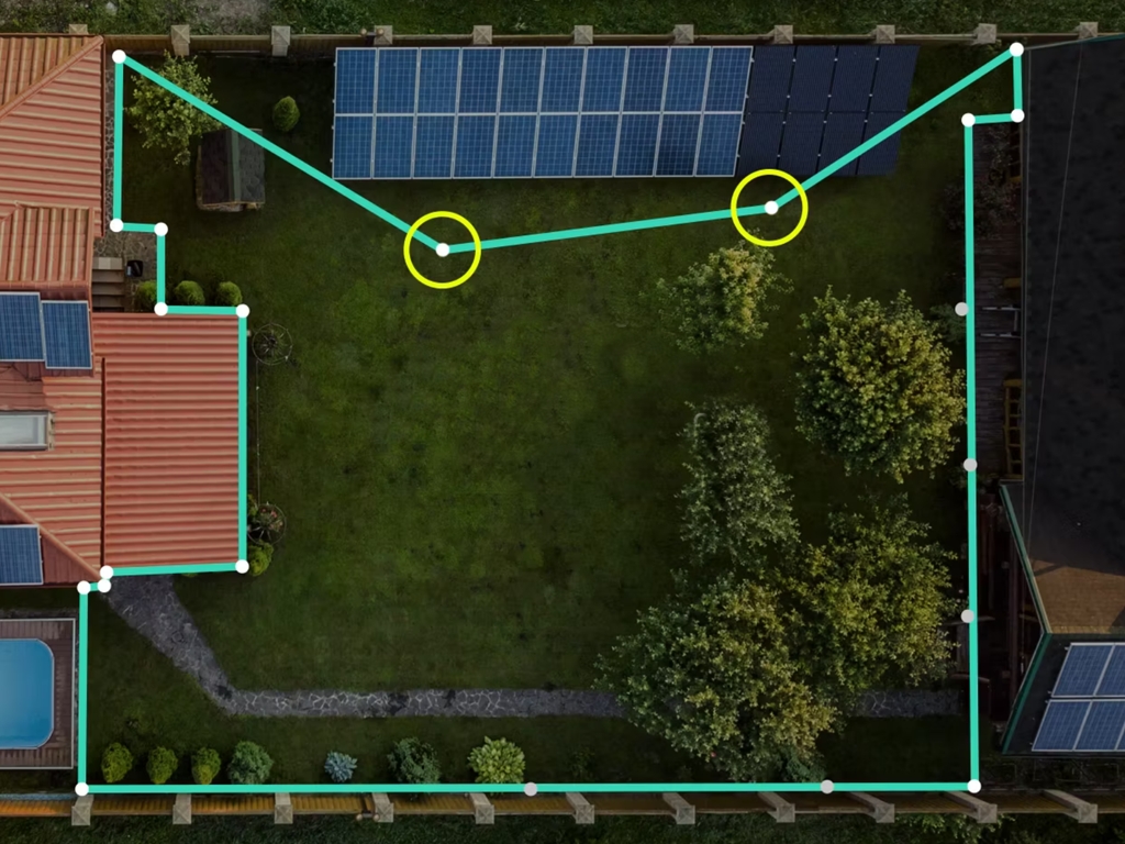


Units: Ensure this is set to the right unit matching the export units set in Moasure.
vanliga tidsramen;
När du är redo att avsluta din första mätning, tryck på '+' ikonen i mitten längst ner på skärmen;
För att skapa ett andra Lager, tryck på 'Lager'-ikonen i det nedre högra hörnet av skärmen och välj 'Lägg till Lager';
Kom ihåg att mätfelet ökar med tiden, inte avståndet.
Pausa var 6–8 sekund under varje mätning.
Försök att hålla en hastighet på minst 1 m per sekund – pausa oftare vid längre mätningar. Använd varje paus för att planera ditt nästa steg.
Använd verktyget 'Ignorera Punkter' i appen för att 'ignorera' enskilda punkter som registrerats under mätningen. När en punkt ignoreras ritas en linje mellan punkterna före och efter den ignorerade punkten (eller punkterna). Använd den här funktionen när du behöver gå runt ett hinder eller när du inte har fri sikt genom ett hinder.
Visa feedbacken från Moasure Coach för att hjälpa dig mäta med både säkerhet och noggrannhet.
Byt vägtyp till Punkter, och samla sedan in höjddata med hjälp av ett spiral- eller sicksackmönster. Använd fler punkter för ojämna eller sluttande ytor.
Gå tillbaka till Punkt C för att registrera din sista punkt och tryck på den röda stoppikonen för att avsluta lagret.
Tryck på X i övre högra hörnet för att avsluta Layers och återgå till arbetsytan.
Tryck på lämplig ruta för att ange dina värden för mindre och större höjdkurvsintervall.
Ange dina valda värden.
Tryck på Spara.
Dina höjdkurvor uppdateras i vyn.
Om det mindre höjdkurvsintervallet är 0,2 m och det större höjdkurvsintervallet är satt till 4 → större höjdkurvor visas var 0,8 m.
Om det mindre höjdkurvsintervallet är 1,0 m och det större höjdkurvsintervallet är satt till 2 → större höjdkurvor visas var 2,0 m.
Växla mellan standardläget ”Lutningsvy” och ”Planvy”:
Lutningsvy visar detaljer om lutningen mellan punkterna, inklusive horisontell sträcka, lutningsprocent, höjdskillnad och vinkel.
Planvy visar en vy uppifrån med horisontell distans mellan punkterna.
Svep nedåt eller tryck på den nedtonade ytan för att återgå till föregående vy.
Tryck på ”Avbryt” för att återgå till din mätning.
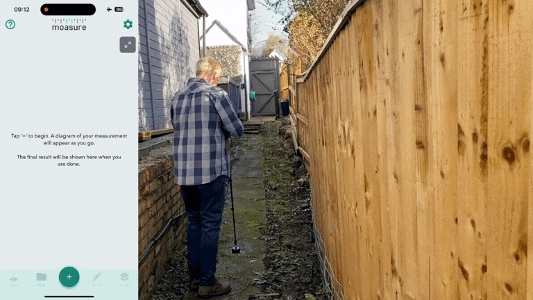
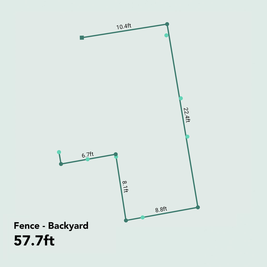
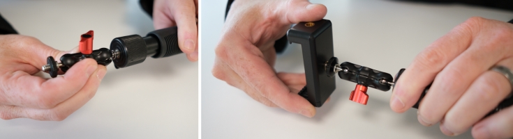
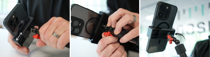


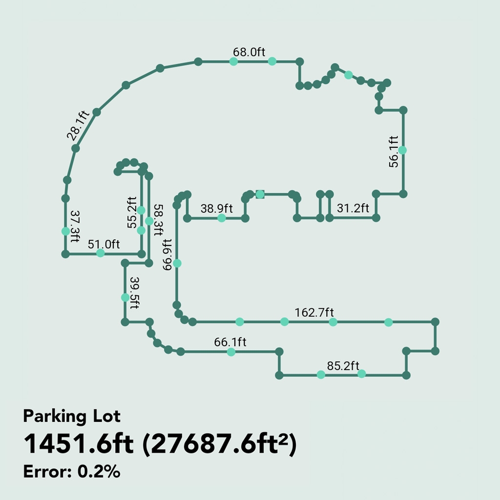


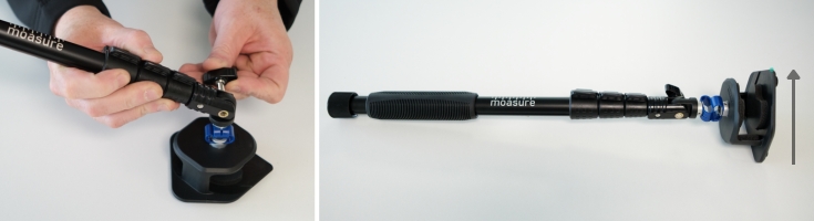


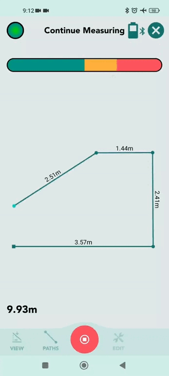


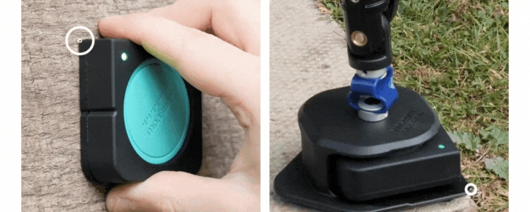
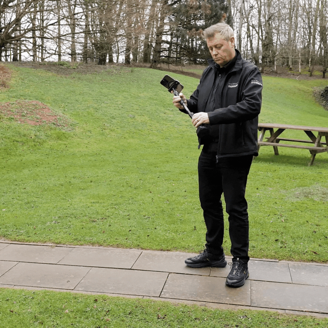
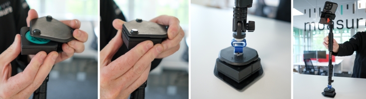
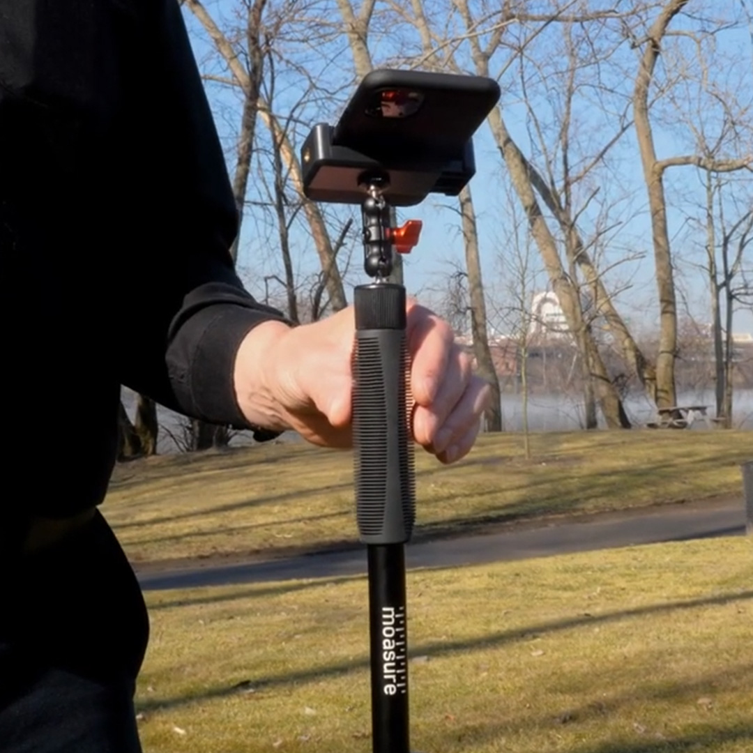


För att starta en mätning, tryck på + ikonen i Moasure-appen.
När du har valt en mättyp, sätt på Moasure-enhet så att Moasure-appen kan ansluta till din enhet.
Med din Moasure-enhet påslagen kommer Moasure-appen att instruera dig att "Placera vid start" – placera enheten på den plats där du vill börja mäta. Genom att hålla Moasure helt stilla markerar du startpunkten för din mätning.
När du börjar röra dig startar Moasure mätningen. Varje gång du placerar enheten och håller den stilla, registreras en punkt – och en linje ritas i Moasure-appen som förbinder denna punkt med föregående punkt. Vi kallar dessa linjer för .
När du har avslutat din mätning, tryck på den röda stoppikonen längst ned i mitten av Moasure-appen.
Din färdiga ritning visas på arbetsytan där du kan se den ur olika perspektiv och .
Rensa arbetsyta
Även om det för närvarande inte finns något direkt alternativ för att rensa arbetsytan, kommer du att skriva över den aktuella mätningen genom att starta en ny mätning genom att trycka på '+'-ikonen eller öppna en sparad mätning. Det är viktigt att notera att nya mätningar eller redigeringar av befintliga mätningar inte sparas automatiskt.
För att säkerställa att dina ändringar sparas, tryck på "Arkiv" och välj sedan "Spara". Appen kommer dessutom att uppmana dig att spara dina framsteg när den upptäcker åtgärder som kan leda till potentiell dataförlust, såsom att starta en ny mätning eller öppna en annan.
I den här guiden kommer du att lära dig hur du exporterar filer, vilka format du kan exportera till och vilka konfigurationsalternativ du kan välja för att anpassa de exporterade filerna.
Ingen (ingen etikett visas)
Mått (en etikett visas som visar längden på sidan/linjen)
Sidnummer (ett referensnummer visas)
Så här ändrar du denna inställning:
Öppna Inställningar genom att trycka på kugghjulsikonen uppe i högra hörnet.
Tryck på Visningsalternativ.
Tryck på Linjeetikettyp under Exportinställningar och välj önskad typ av etikett.
Denna inställning låter dig visa eller dölja etiketter i ritningar. Det motsvarar i praktiken att välja ingen som etikettyp i inställningen Linjeetikettyp.
Så här ändrar du denna inställning:
Öppna Inställningar genom att trycka på kugghjulsikonen uppe i högra hörnet.
Tryck på Visningsalternativ.
Tryck på Visa etiketter i ritningar.
Välj önskat värde (ja/nej).
Etiketterna i PDF-sammanfattningen skiljer sig från sid-/linjeetiketterna. Det är måtten som visas för stig-/linjesidorna i sammanfattningsdelen av PDF-filen.
För att ändra den här inställningen, följ stegen nedan:
Öppna Inställningar genom att trycka på kugghjulsikonen uppe i högra hörnet.
Tryck på Visningsalternativ.
Tryck på Visa etiketter i PDF-sammanfattning.
Välj önskat värde (ja/nej).
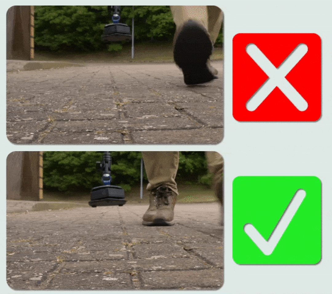
DXF (Drawing Exchange Format) för användning i CAD-program.
CSV (Comma Separated Values) för att visa de råa koordinaterna i ett kalkylblad.
Bild: Du kan exportera till PNG-, JPG- eller SVG-format.
MFile: Exportera till MFile för att dela med en annan Moasure-app.
Öppna Moasure-appen och välj den mätning du vill exportera genom att gå till Filer längst ned i appen och sedan välja Öppna.
När mätningen har laddats, tryck på Arkiv > Exportera.
Välj önskat exportformat från de tillgängliga alternativen.
När du exporterar till PDF kan du välja att ändra de förvalda konfigurationsalternativen för att anpassa PDF efter dina önskemål. Du kan förhandsgranska hur konfigurationsalternativen påverkar PDF innan export genom att trycka på Visa förhandsgranskning längst ned på PDF-konfigurationsskärmen.
De konfigurerbara alternativen förklaras nedan:
Teckenstorlek för dimensioner. Storleken på teckensnittet som används i hela PDF-dokumentet.
Pappersstorlek. Storleken på pappret som PDF kommer att exporteras till. Du kan välja mellan ett brett utbud av alternativ, inklusive A0 till A4, samt tekniska pappersstorlekar som ANSI C till E.
Skala för att passa. Skala för att passa är förvalt aktiverat. Denna alternativ skalar automatiskt ner eller upp mätningen för att passa de valda pappersstorlekens dimensioner. När det är aktiverat analyserar PDF-exportprocessen innehållet och den valda pappersstorleken. Om innehållet är större än den valda pappersstorleken, skalas det ned proportionellt för att passa inom det tillgängliga utrymmet. Detta säkerställer att hela innehållet är synligt och kan skrivas ut på den valda pappersstorleken. Om innehållet däremot är mindre än den valda pappersstorleken, kan "Skala för att passa" skala upp det proportionellt för att maximera användningen av pappersutrymmet. Detta hjälper till att undvika att små innehåll ser för små ut på större pappersstorlekar.
Förinställd skala. Du kan välja en förinställd skala genom att stänga av alternativet Skala för att passa. Du kan sedan välja från ett brett utbud av skalor, från 1:1 till 1:500. Varje export med en vald skala (oavsett om det är Skala för att passa eller Förinställd skala) har en skala-ruta med ett skalaförhållande som visar relationen mellan mätningarna på pappret och motsvarande mätningar i verkliga livet. Det ger en visuell representation av den skala eller förhållande som används för att representera avstånd. För att ge ett exempel: om du har valt en skala på 1:5 betyder det att varje enhet av mätning på pappret (i detta fall 1 cm) representerar en större mätning i verkliga livet (i detta fall 5 cm). Så för varje 1 cm du mäter på pappret, motsvarar det 5 cm i den verkliga världen. För att illustrera detta ytterligare, om du mäter en kant på pappret och den är 4 cm lång, kan du beräkna den verkliga längden genom att multiplicera den med skalfaktorn. I detta fall skulle 4 cm på pappret representera en längd på 20 cm i verkliga livet (4 cm x 5 = 20 cm).
Dessutom visas ett rutnät av rutor bakom mätningen. Dessa rutnät rutor kan användas för att uppskatta storleken på mätningar i verkliga livet. Rutnätet fungerar som en visuell referens, vilket gör att du kan bedöma de relativa storlekarna på mätkanterna och den totala mätningen. Kom ihåg att du alltid kan slå upp det verkliga värdet av mätkanterna på Kantsidan i PDF
Se nedan ett exempel på en PDF som exporteras med alternativet Skala för att passa.
Centera på sidan. Alternativet Centera på sidan är förvalt aktiverat och centrerar mätningen på sidan även om mätningen dras till vänster eller höger på appens duk innan export. När detta alternativ stängs av kommer mätningen inte att vara centrerad. Detta kan vara användbart när du bara vill exportera en del av mätningen (den del som visas på appens duk). Se nedan exempel på samma PDF med alternativet Centera på sidan aktiverat respektive inaktiverat.
Show Grid. This option is selected by default. This option shows a light square grid on the PDF.
Show Layers on Separate Pages. This option is selected by default. When enabled, it will show Layers (in multi layer measurements) on the PDF by rendering each layer on separate pages.
Show Background Image. This option is selected by default. When enabled and when a background image is added to the measurement through the Edit Background Tool, it will add the background image to the PDF.
Show in Black/White. This option enables you to export the PDF in black/white rather than in the default colours. This is useful when you want to export in higher contrast or simply save on ink.
When exporting to CSV, you can choose to change the default configuration options to customise the CSV to your liking.
The configurable options are as followed:
Include Path Number. Adds a column and value for the Path Type number of the recorded point. The number corresponds to the order of the Path Types in the measurement. To give an example; the first Path Type measured will be number 1. If the Path Type is consequently changed (e.g. from Straight Line to Trace Line), the new path number will be 2. If only one Path Type is used in the measurement, all Path Types will have the number 1.
Include Path Type. Adds a column and value for the Path Type of the recorded point. The Path Types in the CSV do not always map to the values in the UI. Below is a mapping table to help you understand the meaning of the CSV values.
Dot2Dot
SmoothTrace
Trace Line (with the option of enabled in settings).
Trace
LastLeg
The dashed line that is sometimes added by the
Null
Include Point Label. Adds a column and value for the Label of the recorded point added through the Edit Label Tool.
Include Point Type. Adds a column and value for the Type of the recorded point (e.g. default, FlightPoint). A Point Type can be one of the following:
Default
This is a normal pause point.
IgnorePoint
This is a normal ignore point.
FlightPoint
This is an exact sample point on a Trace and Smooth Trace Path.
CenterPoint
This is a point on the centre of an Arc/Circle.
ArcPoint
This is a point on an Arc/Circle Path.
Include Layer Name. Adds a column and value for the name of the layer the recorded point is in (e.g Base Layer).
Include Layer Number. Adds a column and value for the layer number. The number corresponds to the chronological order the layers are added in. To give an example; if you have added one layer to your measurement, there will be two layers in total. The first layer (base layer) will be number 1 and the second (added) layer will be number 2.
Include Column Heading. Adds column heading names on the first row.
Include Area. Adds a column and value for the area.
Include Ignored Points. Adds Ignored points to the CSV.
Use Local Number Format. Uses local number formatting for displaying the number values. To give an example; when enabled, a user in the UK will have the square meter number formatted as 150.65 whilst a user in Spain will have the same number formatted as 150,65. See below an example of CSV file and image that is exported with all configuration options enabled.
When exporting to DXF, you can select from two options:
3D. Includes elevation data.
2D. Flattens data by removing elevation.
When exporting to Image, you can select from three options:
PNG.
JPG. Great for optimised file sizes.
SVG. Great for transparent background.
There are no configuration options for MFiles.
Besides exporting single files, you can also export multiple files at once. To do so, follow the steps below.
Tap on File > Multi Export in the bottom toolbar.
Select the files you want to export or select a whole folder.
Select the desired export format from the options provided.


Mätningstypen Layout gör det möjligt att placera ut punkter på plats baserat på angivna koordinater eller genom att använda ett sparat mätdiagram. Detta är användbart för tillämpningar som landskapsplanering, projektering och allmänna mätarbeten.

Alla inmatade koordinater refereras till en referenskant, vilket består av de två första uppmätta punkterna (A och B). Denna referenskant används för att fastställa orientering och skala i det horisontella planet (endast X- och Y-axlarna).
Höjdvärden (Z-axel) används inte för positionering, även om dina koordinater innehåller höjdinformation. Dessa värden ignoreras vid layoutpositionering.
Observera: Moasure använder inte GPS för att positionera punkter. Alla layoutpunkter positioneras i förhållande till dina uppmätta referenspunkter (A och B) med rörelsebaserad mätning, inte satellitbaserade system som GPS.
För mer information, se avsnittet ‘Granska och förhandsvisa’ längre ned.
Öppna Moasure-appen.
Tryck på +-ikonen längst ner på skärmen.
Välj Layout.
Tryck på +-ikonen på skärmen lägg till koordinater för att välja din inmatningsmetod.
Du kan ange koordinater på tre sätt:
Importera CSV – ladda upp en CSV-fil med koordinater.
Importera CAD – importera punkter direkt från en CAD-fil.
Ange manuellt – skriv in koordinater direkt i appen.
Tryck på Import CSV.
Använd filväljaren för att välja en CSV-fil.
Filformatet måste innehålla exakt två kolumner (utan rubriker):
Kolumn 1: X-koordinat
Kolumn 2: Y-koordinat
Du kan visa och ladda ner ett exempel på en CSV-fil nedan:
Tryck på Import CAD.
Välj en DXF- eller DWG-fil.
Konfigurera enheter, tolerans och hantering av dubbla punkter.
Du kan visa och ladda ner en exempel-CAD-fil nedan:
Välj Mata in manuellt och tryck sedan på ‘+’-knappen längst ned till höger på skärmen.
Ange koordinatvärden i det formulär som visas. Ange om dina punkter ska vara:
‘Relativt till startpunkt’ (mätt i förhållande till ursprungspunkten), eller
‘Relativt till senaste punkt’ (mätt i förhållande till den senaste punkten).
Specificera därefter X-, Y- och (radie)toleransen för din koordinat. Toleransinställningen gör det möjligt att ange en radie inom vilken du vill att koordinaten ska hittas. Detta hjälper till att justera noggrannheten utifrån hur exakt positioneringen behöver vara.
Du kan välja mellan tre förinställda radieval:
2 cm: välj detta för hög noggrannhet. Perfekt när du behöver markera en exakt plats och minsta avvikelse är avgörande.
5 cm: detta är ett alternativ med måttlig noggrannhet. Det balanserar precision med ett bredare sökområde och är lämpligt för allmänna ändamål.
10 cm: välj detta för lägsta noggrannhet. Denna inställning täcker det största området och passar när exakta koordinater inte är kritiska och du söker generell närhet.
Välj en tolerans beroende på hur nära du behöver vara målkoordinaterna. En mindre radie ökar precisionen men minskar sökområdet, medan en större radie utökar sökområdet men minskar precisionen.
När du har lagt till koordinater kommer du att kunna visa, redigera och ta bort dem med hjälp av redigerings- och papperskorgsikonerna. När du redigerar en koordinat kan du ändra X-, Y- och toleransradie samt koordinatens position i listan (indexet). Detta är användbart om du vill ändra ordningen på koordinaterna. För att göra detta, tryck helt enkelt på Redigeringsikonen, välj ett nytt positionsnummer i rullgardinsmenyn och tryck på Spara.
När du har matat in alla dina koordinater och är nöjd med dem, tryck på Förhandsvisa. Appen kommer att skissa en ritning för att hjälpa dig kontrollera att datainmatningen är korrekt.
Referenskanten är avgörande för att dina koordinater ska placeras korrekt. Här är en detaljerad förklaring:
Du måste mäta in en referenskant för att referera till de inmatade koordinaterna.
Referenskanten utgörs av de två första uppmätta punkterna, A och B. Dessa punkter är kritiska eftersom de fastställer X-axeln.
De inmatade koordinaterna är relativa till ursprungspunkten, A.
Appen kommer att uppmana dig att mäta in referenskanten innan den guidar dig till de inmatade koordinaterna.
Om du är nöjd med din inmatning, tryck på Fortsätt.
Moasure använder din smartphones kompass för att guida dig till de inmatade koordinaterna. För att detta ska fungera korrekt är det viktigt att du riktar in telefonen i samma riktning som referenskanten. Referenskanten utgörs av de två första punkterna som hjälper till att orientera enheten, med start från ursprungspunkten. När dessa har mätts in fastställs dina X- och Y-axlar. Nu kan du trycka på Klar.
a. Placera en markering vid ursprungspunkten för din referens. Denna markering måste vara lätt att känna igen, eftersom du avslutar vid din första ursprungspunkt.
b. Rikta in enheten genom att röra dig i rask takt från din första referenspunkt till din andra, inom det gröna området på tidsmätaren. Observera att de inmatade koordinaterna är refererade till din ursprungspunkt. Referenskanten visas som en kompass i nedre vänstra hörnet av appen.
c. När detta steg är slutfört kommer du att instrueras att gå vidare till målpunkt 1, vilket motsvarar antingen den första koordinaten i din CSV-fil eller i din manuellt inmatade lista. Målpunkten visas visuellt på skärmen med en ikon i form av ett hårkors.
d. Rotera enheten gradvis, inte abrupt, och placera ner den snabbt men försiktigt. Gå till den första målkoordinaten och säkerställ att du placerar enheten inom det gröna området på tidsmätaren – inte tidigare och inte senare än det bärnstensfärgade området.
e. När enheten har placerats visar appen om den är inom eller utanför målradien (enligt din inmatning). Om enheten är utanför målområdet får du återkoppling om avståndet till målet, samt en streckad linje mellan din nuvarande position och målkoordinaten, med en pil som visar rätt riktning. Om enheten är inom målradien blir hårkorsikonen helt grön och visar en bock. Placera då en markering inom området. Du kommer därefter att instrueras att gå vidare till nästa målpunkt, tills alla punkter är registrerade.
f. När du har fångat in din sista koordinat, återvänd till ursprungspunkten, markerad som 'A'.
Genom att följa dessa steg kan du noggrant sätta ut punkter baserat på angivna koordinater med hjälp av Moasure-appen och Moasure 2 PRO-enheten.
WallPoint
This is a point on a Wall Path.