
Loading...
Loading...
Loading...
Loading...
Loading...
Loading...
Loading...
Loading...
Loading...
Loading...
Loading...
Loading...
Loading...
Loading...
Loading...
Loading...
Loading...
Loading...
Loading...
Loading...
Loading...
Loading...
Loading...
Loading...
Loading...
Loading...
Loading...
Loading...
Loading...
Loading...
Loading...
Loading...
Loading...
Loading...
Loading...
Loading...
Loading...
Loading...
Loading...
Loading...
Loading...
Loading...
Loading...
Loading...
Loading...
Loading...
Loading...
Loading...
Loading...
Loading...
Loading...
Loading...
Loading...
Loading...
Loading...
Loading...
Loading...
Loading...
Loading...
Loading...
Loading...
Loading...
Loading...
Loading...
Loading...
Loading...
Loading...
Loading...
Loading...
Loading...
Loading...
Loading...
Loading...
Loading...
Loading...
Loading...
Loading...
Loading...
Loading...
Loading...
Loading...
Loading...
Loading...
Loading...
Loading...
Loading...
Loading...
Loading...
Loading...
Loading...
Loading...
Loading...
Loading...
Loading...
Bem-vindo ao Guia do Utilizador da Moasure. Aqui encontrará todas as informações necessárias para a configuração e utilização do seu novo dispositivo de medição Moasure bem como as funcionalidades da aplicação Moasure (anteriormente conhecida como aplicação Moasure PRO).
Este video foi concebido para o dotar das competências e técnicas necessárias para tirar o máximo partido do seu dispositivo Moasure.
Este guia oferece flexibilidade para acomodar diversas preferências de aprendizagem, permitindo-lhe navegar de forma independente em cada secção e voltar a consultá-la sempre que necessário.
Como o Moasure utiliza sensores de movimento, como giroscópios e acelerómetros, é importante ter especial cuidado ao rodar o dispositivo.
Quando precisar de rodar o dispositivo para alinhar o ponto de referência com a orientação desejada, deve fazê-lo de forma gradual, nunca de forma brusca. Tal como acontece com impactos ou colisões, rotações bruscas afetam negativamente os sensores do dispositivo, comprometendo a precisão da medição.
Ao rodar o dispositivo Moasure, faça-o gradualmente enquanto se desloca de um ponto para outro.
Descarregar a aplicação no seu dispositivo Android.
Esta configuração permite-lhe definir um tema claro ou escuro.
Para alterar esta configuração, siga estes passos:
Clique em Definições.
Clique em Opções de Visualização.
Clique em Selecionar Tema.
Escolha o seu tema preferido (claro ou escuro).
Nesta seção, mostramos-lhe como enviar um Pedido de Ajuda através da aplicação.
Pode contactar-nos através da aplicação ou através do e-mail [email protected]. Recomendamos que o faça pela aplicação, enviando um Pedido de Ajuda, já que isso nos fornecerá os seus dados de medição, permitindo-nos oferecer o melhor aconselhamento possível.
Para enviar um Pedido de Ajuda pela aplicação, siga estes passos:
Clique em Definições no canto inferior direito da aplicação.
Clique em Enviar Pedido de Ajuda.
Escreva a sua mensagem e clique em Enviar Pedido de Ajuda.
O e-mail será enviado através da sua conta de e-mail predefinida no telemóvel. Depois de confirmado, o pedido será enviado e será redirecionado novamente para a aplicação.
Esta configuração permite-lhe silenciar o áudio da medição.
Para alterar esta configuração, siga estes passos:
Clique em Definições.
Clique em Opções de Medição.
Ative ou desative a opção Silenciar o Áudio da Medição.
Esta configuração permite-lhe ajustar o tamanho da fonte das medições na aplicação. Nota: isto não afeta o tamanho da fonte de outros textos na aplicação.
Para alterar esta configuração, siga estes passos:
Clique em Definições.
Clique em Opções de Visualização.
Clique em Tamanho da Etiqueta, que se encontra na seção Preferências de Visualização e escolha o tamanho de fonte desejado.
Neste artigo mostramos-lhe como selecionar outro dispositivo Moasure na sua conta.
Com o Moasure, pode ter vários dispositivos registados na mesma conta e alternar facilmente entre eles para realizar medições.
Para mudar de dispositivo, siga estes passos:
Clique em Definições.
Clique em Gestão de Dispositivos e Contas.
Clique em Dispositivo, na seção Gestão de Dispositivos.
Verá uma lista de dispositivos. O dispositivo selecionado terá uma marca de verificação no canto inferior direito do ícone do Moasure. Clique noutro dispositivo para alterar o dispositivo selecionado.
Esta configuração permite-lhe definir durante quanto tempo deseja que a ligação do dispositivo Moasure se mantenha ativa quando não está a medir.
O dispositivo Moasure desliga-se automaticamente após 30 segundos de inatividade, para poupar bateria.
Para alterar o tempo de desligar automático do dispositivo Moasure, siga estes passos:
Clique em Definições.
Clique em Opções de Medição.
Clique em Desconexão do dispositivo Moasure e defina o tempo pretendido. Pode escolher entre: trinta segundos, um minuto, dois minutos ou cinco minutos.
Nesta seção, mostramos-lhe como terminar sessão na sua conta Moasure.
Para terminar sessão, siga estes passos:
Clique em Definições.
Clique em Gestão de Dispositivos e Contas.
Clique em Sair.
Primeiros Passos Saiba como montar e utilizar o Moasure STICK, descarregar a aplicação e emparelhar o seu dispositivo Moasure.
Dispositivo Moasure Aprenda a utilizar o dispositivo Moasure. Os tópicos incluem técnica de medição, precisão e muito mais.
Aplicação Moasure Saiba como utilizar as funções da aplicação Moasure, incluindo ferramentas de edição, guardar e exportar medições.
Casos de Utilização
Saiba mais sobre casos de uso comuns do Moasure com guias mais pormenorizados sobre como medir determinados sítios.


Com o Moasure 2 PRO, pode selecionar o modo de medição que melhor se adapta às suas necessidades:
Máxima exatidão (6-8 segundos): garante a máxima precisão com intervalos mais curtos entre pontos de pausa.
Tempo máximo (12-16 segundos): permite realizar intervalos mais longos entre pontos de pausa, com menor precisão.
Faça pausas a cada 6-8 segundos (pause dentro da zona verde e nunca para além da zona âmbar). Opção indicada para utilizadores que procuram a maior precisão possível na medição.
Faça pausas a cada 12-16 segundos (pause dentro da zona verde e nunca para além da zona âmbar).
Esta opção permite caminhar mais entre os pontos de pausa, mas com redução da precisão em comparação com a opção de 'Máxima precisão'.
Para obter a maior exatidão possível nas suas medições, siga estas três técnicas essenciais:
desloque-se a um ritmo rápido entre os pontos de pausa.
coloque o dispositivo Moasure no solo de forma rápida e suave.
rode o dispositivo gradualmente, não de forma brusca, para evitar leituras imprecisas dos sensores.
Para mudar o Tempo de Medição / Exatidão, siga estes passos:
Clique em Definições no canto inferior direito da aplicação.
Clique em Opções de Medição.
Clique em Tempo Mínimo de Pausa.
Escolha entre obter a máxima precisão ou maior tempo entre pontos de pausa.
Cada medição é composta por 'Pontos' e 'Lados'. Os 'Pontos' são geralmente aqueles em que colocou o dispositivo Moasure sobre a superfície e o deixou imóvel, e os 'Lados' são as linhas que conectam os pontos.
Pode selecionar qualquer ponto do plano para consultar/ver as coordenadas. Uma vez selecionado um ponto, poderá ver as seguintes coordenadas:
X
Y
Z
Ângulo
Pode selecionar qualquer lado do plano para consultar/visualizar:
Comprimento
Altura
Distância Horizontal
Inclinação
O ponto de referência é o ponto a partir do qual o seu dispositivo Moasure mede. Por defeito, o ponto de referência de medição está localizado na parte mais pontiaguda do dispositivo, no lado oposto do indicador LED.
Se estiver a utilizar o Moasure juntamente com o Moasure STICK, é necessário mover o ponto de referência de medição para a parte mais pontiaguda da caixa, de modo a manter a precisão das suas medições.
Para o fazer, siga estes passos:
Clique em Definições (na margem inferior direita da aplicação);
Clique em Opções de Medição;
Ative a opção Utilizar o Moasure STICK.
Nesta seção, irá aprender como alterar o sistema de unidades e a precisão decimal.
Para alterar as unidades de medida, siga estes passos:
Clique em Definições.
Clique em Unidades de Medida.
Selecione a unidade de medida que pretende, tocando sobre ela. Pode escolher entre Métrico e Imperial.
Pode ajustar a precisão decimal – ou seja, o número de dígitos apresentados – para as seguintes unidades:
Linear (metros/pés)
Área (metros quadrados/pés quadrados)
Ângulo (graus)
Inclinação (percentagem)
A ferramenta Quadrar permite ajustar os ângulos da sua medição. Isto é útil em medições de divisões, quando pretende que as paredes e os ângulos sejam ajustados para 90° ou 45°.
Pode alterar a intensidade da ferramenta Quadrar. Existem três níveis:
Baixa
Média
Alta
Clique em Editar.
Clique em Quadrar.
Selecione o nível de intensidade pretendido.
Quanto maior a intensidade, maior a probabilidade de os ângulos serem ajustados para 45° ou 90°.
Nesta seção irá aprender a dominar a técnica de medição. Esta seção é composta por três partes:
Se preferir ler em vez de ver o vídeo, pode clicar nos links abaixo para saber mais sobre como dominar o ritmo, a colocação e a rotação ao medir com o Moasure:
Esta ferramenta permite-lhe ignorar automaticamente todos os pontos indesejados numa linha reta.
Para aplicar esta definição a todas as medições, siga estes passos:
Clique em Definições.
Clique em Opções de Medição.
Ative a opção Ignorar Pontos Automaticamente na seção 'Edição Automática'.
Uma vez ativada, esta configuração adiciona ícones dos módulos do Moasure à medição para mostrar como o dispositivo Moasure estava orientado ao ser colocado sobre o terreno.
Para alterar esta configuração, siga estes passos:
Clique em Definições.
Clique em Opções de Visualização.
Clique em Mostrar/Ocultar Módulos em Diagramas e selecione se pretende que sejam exibidos ou não.
Neste tutorial, mostramos-lhe passo a passo como calcular com precisão a área e o perímetro de um caminho de acesso. Além disso, aprenderá a utilizar a função de Camadas, que vai permitir referenciar vários elementos no mesmo plano.
O Moasure permite-lhe medir círculos e arcos com facilidade. Assista ao nosso breve vídeo tutorial para aprender a medir o raio, o diâmetro, a circunferência e até calcular a área de um círculo.
Capture 3 ou mais pontos à volta de um círculo para medir o raio, o diâmetro, a circunferência ou a área de um círculo. O Tipo de Rota ‘Arco’ permite-lhe medir com a mesma facilidade o comprimento do arco, o ângulo do arco e a área do segmento.
Tome pelo menos 3 pontos no limite do círculo ou do arco.
Todos os pontos devem estar na circunferência ou no limite do arco.
Distribua os pontos ao longo da maior parte possível do perímetro do círculo.
Descubra como ligar o seu dispositivo Moasure com a aplicação complementar.
Quando abrir a aplicação Moasure pela primeira vez, ser-lhe-á pedido que ligue e emparelhe o seu dispositivo.
Nesta guia irá aprender sobre a importância de colocar o Moasure sobre a superfície de forma a que fique completamente imóvel. Também irá aprender como o fazer em terrenos irregulares.
Para evitar sobrecarregar os sensores, é importante colocar o dispositivo Moasure suavemente sobre a superfície e certificar-se de que fica totalmente imóvel. Assim que o dispositivo estiver imóvel, o Moasure capturará um ponto que contém as coordenadas X, Y e Z. O indicador LED do dispositivo ficará verde fixo para indicar que o ponto foi registado com sucesso e que pode continuar a medição ou terminá-la.
Se estiver a medir com o Moasure STICK, é altamente recomendável segurá-lo com o polegar e os dois primeiros dedos, em vez da palma da mão. Segurar o STICK com os dedos ajuda a pousar o dispositivo suavemente sobre a superfície.
Esta ferramenta permite-lhe adicionar uma imagem de fundo à sua medição.
Pode utilizar esta ferramenta para mostrar a clientes ou colegas de trabalho uma visualização do projeto medido em relação a uma área fotografada, uma vez que a medição será sobreposta à imagem de fundo.
Para adicionar uma imagem de fundo à sua medição, siga estes passos:
Com a medição aberta, clique em 'Editar'.
O vídeo a seguir oferece um guia rápido e prático do Menu de Edição do Moasure, mostrando quando e como usar as , como Abrir/Fechar, Quadrar, Anotar, Corte/Aterro, Adicionar Profundidade e outras, para organizar, esclarecer e finalizar uma medição antes de exportá-la ou partilhá-la.
Esta ferramenta permite-lhe ignorar automaticamente todos os pontos indesejados numa linha reta.
À medida que coloca o seu dispositivo Moasure sobre a superfície durante uma medição, em intervalos de 6 a 8 segundos, a aplicação Moasure regista um ponto (uma coordenada com os valores X, Y e Z).
A ferramenta Ignorar Automaticamente permite ignorar os pontos intermédios numa linha reta. Quando um ponto é ignorado, o ponto anterior é ligado ao seguinte através de uma linha reta.
A função de Anotação permite-lhe adicionar notas em qualquer parte do espaço de trabalho, sem que estejam vinculadas a um ponto de medição específico.
Além de adicionar a pontos individuais, também pode colocar anotações diretamente no espaço de trabalho para fornecer contexto adicional, destacar áreas específicas ou documentar observações.
Isto é útil, por exemplo, para:
marcar seções de um parque infantil;
identificar riscos:
A ferramenta Editar Rotas permite alterar os Tipos de Rotas medidos originalmente.
Por exemplo, pode:
Alterar o tipo de rota de 'Linha Reta' para 'Traçar/Linha de Seguimento';
Alterar o tipo de rota de 'Ignorar Ponto' para 'Linha Reta';
Criar um círculo ou um arco com base em dois tipos de rotas e um ponto.
Descubra o impacto que o ritmo tem no resultado final da medição.
Com a tecnologia de medição baseada no movimento, o erro de medição aumenta exponencialmente com o tempo, e não com a distância. Isto significa que deve deslocar-se rapidamente de um ponto para outro e rodar o dispositivo de forma gradual.
Para minimizar o erro e maximizar a precisão da medição, tente fazer pausas antes de ultrapassar os 8 segundos. Fazer uma pausa significa colocar o dispositivo Moasure sobre uma superfície e mantê-lo imóvel durante, pelo menos, 1 segundo para capturar o ponto. Isto não significa que tenha de completar toda a medição em 8 segundos — pode realizar tantas pausas quantas forem necessárias até concluir a medição.
Para o ajudar a manter-se dentro da faixa de tempo de 0 a 8 segundos, a aplicação Moasure dispõe de uma barra de tempo e de sinais sonoros.
Aprenda como medir através ou em redor de obstáculos e obstruções com o Moasure.
Assista a este breve tutorial sobre como utilizar tanto a ferramenta como a ferramenta para medir espaços complexos.
Os obstáculos ou obstruções podem parecer um desafio ao medir com o Moasure, já que a medição baseada no movimento exige uma pausa a cada 6-8 segundos. No entanto, a aplicação Moasure disponibiliza a poderosa ferramenta 'Ignorar', que oferece uma forma rápida e simples de medir através de obstáculos como se estes não existissem.
No exemplo seguinte, o jardim traseiro tem grandes painéis solares colocados ao longo do perímetro, o que impede a medição mesmo junto à borda do relvado. Graças à ferramenta 'Ignorar' dentro da aplicação Moasure, é possível medir em redor do obstáculo, capturando pontos à medida que avançamos até chegar ao outro lado. Depois, quando regressamos ao ponto inicial da medição para completar o levantamento do espaço, podemos usar a ferramenta 'Ignorar' para eliminar os pontos indesejados do desenho da medição.
Depois de ignorar um ponto, a aplicação desenhará uma linha entre o ponto anterior e o seguinte. Pode fazer pausas e capturar tantos pontos quanto necessitar para medir em redor de um obstáculo. Da mesma forma, pode ignorar ou eliminar a quantidade de pontos que considerar necessária para criar uma medição precisa e o respetivo desenho de um espaço.
O vídeo seguinte demonstra como a utilização da ferramenta 'Ignorar' elimina, na prática, os pontos de medição.
Se estiver a utilizar o dispositivo Moasure juntamente com o acessório Moasure STICK, pode informar a aplicação através do menu de Definições para modificar o ponto de referência da medição.
Se desejar usar o Moasure STICK para medir, recomendamos que informe a aplicação Moasure dessa utilização, de modo a maximizar a precisão.
Por defeito, o do Moasure encontra-se na parte mais pontiaguda do dispositivo. No entanto, se ativar a opção 'Acessório Moasure STICK' nas definições, o ponto de referência passará a ser a parte mais pontiaguda do STICK, em vez do dispositivo.
Esta configuração permite-lhe desativar a análise de dados. Esta opção vem ativada por defeito.
Para alterar esta configuração, siga estes passos:
Clique em Definições.
Neste artigo vai aprender como alterar o modo de ligar o dispositivo Moasure.
O Moasure permite dois métodos de ligação:
Toque Duplo – é necessário tocar duas vezes no dispositivo para o ligar.
A Calculadora de Áreas simplifica e agiliza o processo de cálculo da área líquida entre várias camadas. Esta função é especialmente útil quando precisa de determinar a área entre camadas, como por exemplo:
Áreas de paisagismo menos áreas de plantação.
Superfícies de parques infantis excluindo caminhos.
Uma área de piscina subtraída de um deck/terraço circundante
Neste vídeo, mostramos-lhe como medir duas áreas verdes com o Moasure, utilizando as suas poderosas funções de Volume e Traçado de Linhas. Descubra como o Moasure mede a Área e o Volume para o nivelamento de superfícies e como traça formas irregulares facilmente.
Assista a uma demonstração do Moasure ao ar livre.
Esta configuração permite-lhe ocultar as sugestões de melhoria do Instrutor do Moasure e personalizar o tipo de comentários que pretende receber.
O Instrutor do Moasure tem como objetivo ajudá-lo a melhorar as suas medições, dando-lhe conselhos e sugestões sobre como aperfeiçoar o processo. Também realça as seções das medições que podem ser otimizadas. Se preferir não ver estas sugestões, pode desativar determinados tipos de comentários ou ocultar todos os comentários.
Para alterar esta configuração, siga estes passos:
Clique em Definições.
Clique em Opções de Exibição.
Neste vídeo mostramos-lhe como medir um jardim irregular, cheio de obstáculos. Graças à tecnologia do Moasure, é possível medir cantos inacessíveis utilizando funções avançadas como 'Extrapolar Canto'. Além disso, mostramos como medir sem o Moasure STICK pode facilitar o trabalho de campo em terrenos muito irregulares, permitindo chegar a zonas de difícil acesso noutras circunstâncias.
Use o Tipo de Rota ‘Parede’ para medir rapidamente contornos de edifícios ou divisões.
Neste artigo mostramos-lhe como remover um dispositivo Moasure.
Para remover um dispositivo Moasure, siga estes passos:
Clique em Definições.
Clique em Gestão de Dispositivos e Contas.
Clique em Preferências do Dispositivo, que se encontra na seção Gestão de Dispositivos.
Nesta seção, mostramos-lhe como repor as definições da aplicação Moasure. As suas medições não serão eliminadas.
Para repor as definições, siga estes passos:
Clique em Definições.
Exportação (metros/pés – pode ser configurada de forma diferente da definição linear, permitindo que a exportação seja apresentada de forma distinta da medição na aplicação).
Clique em Habilitar Análise.
Selecione 'Sim' ou 'Não'.
Rotação – permite ligar o dispositivo segurando-o na vertical e rodando-o 180 graus de um lado para o outro até que o indicador LED comece a piscar a azul. Pode encontrar mais informações aqui.
Para alterar o método de ligação, siga estes passos:
Clique em Definições.
Clique em Gestão de Dispositivos e Contas.
Clique em Preferências do Dispositivo.
Ative o seu dispositivo Moasure. O dispositivo precisa de estar ligado para poder efetuar alterações. Assim que estiver ativo, poderá ver os dados do dispositivo no ecrã.
Clique no método de ligação atual e selecione o que deseja utilizar.
Na seção Instrutor do Moasure, clique em Mostrar Sugestões do Instrutor e selecione 'Não' se desejar ocultar todas as sugestões de melhoria. Se preferir ocultar apenas comentários específicos, selecione 'Sim' e clique em Preferências, onde poderá desativar os comentários que não quiser receber.
Clique em Remover este dispositivo.
Confirme a ação clicando em Sim.
Confirme que deseja continuar com esta ação, clicando em Redefinir Configurações.
Como Criar Camadas
Como Calcular a Área de Camadas
Como Adicionar o Volume como uma Camada Adicional
Camadas de Cores
Clique em Definições.
Clique em Opções de Medição.
Clique em Como Começar uma Medição e selecione o Tipo de Rota desejado.


A seguir, encontrará mais informações sobre os dados que armazenamos ao criar uma conta e sobre como eliminar a sua conta, o que irá anonimizar todos os dados a ela associados.
Quando regista uma conta na aplicação Moasure, armazenamos o seu nome e o endereço de e-mail. As medições, imagens de fundo e as fotos/logótipos da conta são guardados no seu dispositivo e não são acessíveis nem partilhados pela 3D Technologies / Moasure.
Para melhorar a experiência do utilizador e para fins de investigação, recolhemos dados sobre as interações com a aplicação. No entanto, pode desativar a análise de dados. Recorde que a análise de dados permite-nos oferecer-lhe um melhor aconselhamento quando nos envia um Pedido de Ajuda.
Para eliminar a sua conta, siga estes passos:
Clique em Definições.
Clique em Gestão de Dispositivos e Contas.
Clique em Remover Conta.
Confirme esta ação introduzindo a sua palavra-passe e, de seguida, clicando em Excluir.
Depois de concluir estes passos, todos os dados associados à sua conta (nome e endereço de e-mail) serão completamente anonimizados.
Se tiver algum problema ao seguir os passos anteriores, pode contactar a nossa Equipa de Apoio ao Cliente através de [email protected] para solicitar a eliminação dos seus dados.
As preferências de exportação permitem-lhe configurar o aspeto das suas exportações em PDF e em formato de imagem.
O Tipo de Etiqueta de Linha permite-lhe configurar a etiqueta que é mostrada num lado ou linha de uma medição. Pode escolher entre as seguintes opções:
Nenhuma: não será mostrada qualquer etiqueta.
Dimensões: será mostrada uma etiqueta com o comprimento do lado ou linha.
Número do Lado: será mostrado um número de referência.
Para alterar esta configuração, siga estes passos:
Clique em Definições.
Clique em Opções de Visualização.
Clique em Tipo de Etiqueta de Linha e selecione o tipo de etiqueta desejado.
Esta opção permite-lhe mostrar ou ocultar etiquetas nos desenhos/plantas, tendo o mesmo efeito que escolher “nenhuma” como Tipo de Etiqueta na configuração de Tipo de Etiqueta de Linha.
Para alterar esta configuração, siga estes passos:
Clique em Definições.
Clique em Opções de Visualização.
Clique em Mostrar Etiquetas nos Desenhos.
Selecione 'Sim' ou 'Não'.
As etiquetas no PDF são diferentes das etiquetas dos lados ou linhas. Estas mostram as dimensões dos lados na primeira página do PDF.
Para alterar esta configuração, siga estes passos:
Clique em Definições.
Clique em Opções de Visualização.
Clique em Mostrar Etiquetas no Resumo PDF.
Selecione 'Sim' ou 'Não'.
A Moasure possui uma API de Ligação de Aplicação/Ligação Profunda para permitir que os nossos parceiros desenvolvam funções de ligação profunda. Isto permite que os nossos parceiros, por exemplo, criem um botão na sua aplicação para iniciar uma medição, que ao ser clicado abrirá a aplicação Moasure e iniciará a medição imediatamente. Uma vez concluída a ação, a aplicação Moasure redirecionará o utilizador de volta para a aplicação do nosso parceiro com os dados relevantes que poderão ser processados pela aplicação do nosso parceiro. Outras operações também são suportadas.
Para aceder à API, envie-nos um e-mail para [email protected].
A Moasure ainda não dispõe de uma API de serviço web de acesso público. Se estiver interessado nisso, envie-nos um e-mail para [email protected].
Dispositivos Android: requer permissões de Bluetooth e Localização. A localização é utilizada para calibrar o seu dispositivo Moasure com base na gravidade.
Para conceder permissões, basta clicar nos botões da aplicação. Por exemplo, para conceder permissões de Bluetooth, clique no botão Ativar e Permitir Bluetooth.
Ligue o seu dispositivo Moasure a uma fonte de alimentação através do cabo USB.
A aplicação procurará automaticamente o seu dispositivo através de Bluetooth. Uma vez detetado, o seu dispositivo será listado em Dispositivos Disponíveis.
Seleccione o seu dispositivo na lista para o ligar à aplicação complementar.
O seu dispositivo estará agora liado à aplicação e pronto para começar a medir.
Para garantir uma ligação perfeita entre o seu dispositivo Moasure e a aplicação, siga estes passos:
Ative o Bluetooth: Nas definições do seu smartphone, certifique-se de que o Bluetooth está ativado. Desativar o Bluetooth impedirá que a aplicação Moasure se ligue ao seu dispositivo Moasure.
Verifique as permissões da aplicação: Se tiver problemas de ligação apesar de ter o Bluetooth ativado, verifique as permissões de Bluetooth para a aplicação Moasure. Se a permissão Bluetooth estiver desativada para a aplicação, não será possível estabelecer ligação ao seu dispositivo Moasure. Conceda as permissões necessárias para resolver este problema.
Os dispositivos Moasure incluem baterias recarregáveis concebidas para satisfazer as suas necessidades de medição durante todo o dia.
Moasure 2 PRO: Aproximadamente 10 horas de utilização contínua.
Moasure 2: Aproximadamente 5 horas de utilização contínua.
Moasure ONE: Aproximadamente 5 horas de utilização contínua.
Para garantir o melhor desempenho, certifique-se de carregar completamente o seu dispositivo Moasure antes de o utilizar.
Se planeia passar o dia inteiro a medir, ou se simplesmente deseja verificar o nível da bateria do seu dispositivo Moasure, pode fazê-lo através da aplicação seguindo estes passos:
Ligue o seu dispositivo Moasure.
Abra a aplicação Moasure.
Inicie uma nova medição.
O indicador de nível de bateria aparecerá no canto superior direito do ecrã.
Moasure 2 e Moasure 2 PRO:
Tipo de cabo: Utilize cabos USB Tipo-C.
Especificações do carregador: Utilize um carregador que cumpra os requisitos do padrão USB Tipo-C para um desempenho ótimo.
Moasure ONE:
Tipo de cabo: Utilize um cabo Micro USB.
Especificações do carregador: Recomenda-se utilizar sempre o cabo USB fornecido. Se necessitar de usar outro cabo, assegure-se de que é um carregador micro-USB padrão com saída de 5 V e uma capacidade mínima de corrente de 500 mA.
Carregadores com maior capacidade de corrente não trarão benefícios adicionais.
Carregadores com voltagem superior a 5 V (como 9 V ou 12 V) danificarão o dispositivo.
Carregadores com voltagem inferior não carregarão o dispositivo.
Quando a bateria do seu dispositivo Moasure estiver fraca, a aplicação Moasure irá notificá-lo para o carregar.
Para todos os dispositivos, assegure-se de utilizar o tipo de cabo e as especificações de carregador corretos para preservar a durabilidade e o desempenho do seu Moasure.
Consoante o terreno onde esteja a medir, pode haver diferentes graus de dificuldade em manter o dispositivo Moasure imóvel. Seguem-se alguns conselhos para várias situações.
Em superfícies como relva natural ou relva artificial, pode ser difícil manter o dispositivo Moasure totalmente imóvel.
Em terrenos irregulares, pressionar o Moasure STICK para baixo com suavidade ajudará a manter o dispositivo imóvel para que o ponto possa ser registado. No entanto, em alguns casos, poderá ser mais adequado medir sem o STICK, especialmente quando a relva é muito alta, por exemplo.
Medir sem o STICK permite-lhe ter maior controlo sobre a colocação do Moasure utilizando os dedos.
Numa superfície inclinada, como uma colina ou uma rampa, o peso do STICK pode, por vezes, fazer com que o Moasure se mova ligeiramente. Esse movimento dificulta a captura de um ponto.
Para manter o dispositivo totalmente imóvel e garantir o registo do ponto, deixe que o STICK repouse entre o polegar e o dedo indicador.
Segure o Moasure STICK com o polegar e os dois primeiros dedos, em vez da palma da mão: isto evita que oscile e ajuda a colocar o dispositivo Moasure sobre a superfície com mais suavidade.
Coloque o dispositivo com firmeza. Evite manter o Moasure STICK suspenso sobre o ponto onde pretende colocá-lo.
Lembre-se de que, embora possa parecer contraintuitivo, quanto mais rapidamente se deslocar de um ponto para outro e pousar o dispositivo na superfície, maior será a precisão da medição.
Coloque o dispositivo com suavidade: evite pancadas, choques ou impactos, pois afetam negativamente os sensores do Moasure.
Em terrenos irregulares, pressione o Moasure STICK suavemente para baixo, de modo a manter o dispositivo imóvel e permitir o registo do ponto.
Em terrenos inclinados, deixe que o STICK repouse entre o polegar e o dedo indicador. O peso do STICK, por si só, ajudará a manter o dispositivo completamente imóvel para que o ponto possa ser registado.
No vídeo seguinte pode ver como medir em diferentes superfícies. O vídeo também mostra como dominar o ritmo e a rotação.
Clique em 'Editar Imagem de Fundo'.
Clique em 'Adicionar Imagem'.
De seguida, poderá selecionar uma imagem guardada no seu telemóvel para a usar como fundo.
Assim que selecionar a imagem, esta será carregada na aplicação Moasure e utilizada como imagem de fundo.
Será mostrado um Seletor de Imagens, permitindo escolher a imagem desejada do seu dispositivo. Uma vez selecionada, a imagem será carregada e aplicada como fundo.
Uma vez adicionada a Imagem de Fundo, pode editá-la com as seguintes ferramentas disponíveis:
Rodar – gira a imagem +90°. Clique no segundo ícone da esquerda na barra de ferramentas (canto superior direito).
Zoom – aproxime ou afaste a imagem com o gesto de pinça (polegar e indicador).
Arrastar – toque na imagem com o dedo e mova-a para a esquerda ou direita.
Recortar – corta a imagem de fundo. Clique no segundo ícone da direita na barra de ferramentas (canto superior direito). Tudo o que ficar fora das margens brancas será recortado.
Alterar Opacidade – ajusta a transparência da imagem. Clique no primeiro ícone da direita na barra de ferramentas e deslize o botão para a esquerda/direita até obter a opacidade desejada.
Repor – restaura todos os ajustes feitos na imagem e no plano desde a sua adição.
Por defeito, a imagem de fundo está selecionada. No entanto, também pode rodar, arrastar e aplicar zoom ao plano/desenho.
Para isso:
Selecione o plano clicando no ícone situado no canto inferior direito.
Uma vez selecionado, poderá rodar, arrastar e aplicar zoom ao plano em relação à imagem de fundo através de gestos táteis.
Pode sempre voltar à imagem de fundo para continuar a editá-la.
Clique em Editar.
Selecione Ignorar Automaticamente.
Para restaurar um ponto ignorado, basta selecionar o ponto e clicar em 'Não Ignorar' (disponível no menu Editar).
As anotações podem ajudar a tornar as medições mais claras e fáceis de compreender ao partilhá-las com colegas, empreiteiros ou clientes.
Clique em 'Editar'.
Clique em 'Anotação'.
Escreva o texto da sua anotação e clique em 'Aplicar'.
Arraste com um dedo para mover a anotação para o local desejado.
Use o gesto de pinça com dois dedos para ampliar/reduzir ou rodar a anotação.
Clique em qualquer parte do plano para desselecionar e fixar a anotação no lugar.
As anotações permanecem legíveis mesmo quando a medição é rodada.
Clique uma vez sobre a anotação.
Clique em 'Editar' → 'Anotação'.
Edite o texto e clique em 'Aplicar' para guardar as alterações, ou use o ícone do caixote do lixo para eliminá-la.
As anotações podem ser adicionadas nas Vistas em Planta 2D e Planta Ajustada 2D, e são visíveis tanto em Vistas 2D como em 3D.
Atualmente, não são compatíveis com as Vistas de Curvas de Nível nem com a Vista de Superfície 3D.
As anotações são incluídas na exportação para CAD e PDF.
Clique em Editar na parte inferior da aplicação.
Clique em Editar Rotas.
No ecrã de Editar Rotas, verá que cada rota tem uma cor diferente, ajudando a identificar quais são distintas entre si.
Selecione uma rota, tocando sobre ela.
Clique em Alterar Tipo de Rota.
Selecione o Novo Tipo de Rota para substituir o tipo de rota selecionado.
Para dividir ou unir rotas, siga estes passos:
Clique em Editar na parte inferior da aplicação.
Clique em Editar Rotas.
No ecrã de Editar Rotas, verá que cada rota tem uma cor diferente, para que saiba distinguir quais são diferentes entre si.
Selecione um ponto, tocando sobre ele.
Clique em Dividir Rota ou Unir Rota.
As rotas serão divididas ou unidas no ponto selecionado.
Faixa branca: de 0 a 6 segundos
Faixa âmbar: de 6 a 8 segundos
Faixa vermelha: a partir de 8 segundos
Embora possa parecer contraintuitivo, quanto mais rapidamente se mover de um ponto para outro, maior será a precisão da medição.
Além das indicações visuais da barra de tempo, também receberá avisos sonoros:
Um tic lento surge aos 6 segundos.
O som acelera para um tic rápido aos 8 segundos.
Assim que ouvir o tic lento, deve preparar-se para colocar o dispositivo numa superfície e capturar um ponto.
Não se preocupe se não conseguir contornar um obstáculo em 8 segundos. Pode fazer tantas pausas quantas forem necessárias, pelo tempo que precisar, até conseguir ultrapassar a obstrução.
Se não quiser que esses pontos de pausa fiquem registados no plano, pode alterar o Tipo de Rota para 'Ignorar Linha' antes de contornar o obstáculo.
Outra forma é utilizar a ferramenta 'Ignorar' depois de concluir a medição, para eliminar pontos auxiliares. Sempre que ignorar um ponto, o ponto anterior será ligado ao seguinte.
Se preferir ver em vez de ler, pode assistir a um vídeo que aborda os três aspetos fundamentais para dominar a técnica de medição.
Saiba mais sobre a ferramenta 'Ignorar'.
Clique em Definições.
Clique em Opções de Visualização.
Clique em Formato da Grelha (2D).
Escolha o seu tipo de grelha preferido:
Sem grelha
Planta (sem escala)
Linhas principais
Linhas principais e secundárias
Um visto verde aparecerá junto ao tipo de grelha selecionado.
Clique na seta para trás, no canto superior esquerdo, para regressar ao ecrã principal.
As Opções de Grelha melhoram a visualização e a usabilidade das medições, proporcionando uma referência rápida da dimensão real da área medida. Esta função é útil para os utilizadores que necessitam de uma indicação visual precisa da escala dentro do seu ambiente de medição.
Clique em Definições.
Clique em Opções de Medição.
Clique em 'Utilizar Moasure STICK'.
Selecione 'Sim'.
A partir desse momento, a parte mais pontiaguda do Moasure STICK será utilizada como o novo Ponto de Referência.
Para que a Calculadora de Áreas funcione, é necessário ter pelo menos duas camadas com medições de área.
Abra a Calculadora de Áreas.
Clique em Camadas para mostrar a lista de camadas da medição.
Clique em Calculadora de Áreas na parte superior do ecrã.
A área de cada camada é mostrada por baixo do respetivo nome.
A Área Líquida entre camadas aparece na parte inferior.
Use os dedos para arrastar e largar uma camada na seção Camadas Subtraídas.
Em alternativa, clique na seta para baixo junto à camada que pretende subtrair.
A Área Líquida será atualizada automaticamente à medida que move as camadas.
Use os dedos para arrastar e largar uma camada da seção Camadas Subtraídas para a seção Camadas Base.
Alternativamente, clique na seta para cima para mover uma camada novamente para as Camadas Base.
Para remover uma camada do cálculo por completo, clique no ícone do olho para ativar ou desativar a sua visibilidade.
Esta ferramenta é útil para diversas aplicações, como:
Paisagistas que precisam de calcular a área total do relvado menos os canteiros de flores.
Designers de piscinas que necessitam de subtrair a camada da piscina da área do terraço, obtendo assim o valor da área entre ambas.
Designers de parques infantis que precisam de determinar a área combinada da zona de jogos menos as secções de asfalto que as ligam.
Nesta seção, irá aprender como ligar e desligar o seu dispositivo Moasure.
IMPORTANTE O método para ligar o seu dispositivo Moasure depende do modelo e da configuração do dispositivo.
Moasure 2 e Moasure 2 PRO: Estes modelos apenas se ligam por Rotação.
Moasure ONE: Este modelo permite ligar tanto por Toque Duplo como por Rotação. Por predefinição, o método de ligação é Toque Duplo, mas pode alterá-lo para Rotação se tiver a versão de firmware 1.28 ou superior.
Com STICK: Levante o STICK na posição vertical e rode-o 180° de um lado para o outro até que o indicador LED comece a piscar a azul.
Sem STICK: Segure o dispositivo entre o polegar e o indicador, levante-o na posição vertical e rode-o 180° de um lado para o outro até que o indicador LED comece a piscar a azul.
Com STICK: Coloque o STICK sobre uma superfície plana e sólida, depois dê dois toques na parte superior do canto pontiagudo do seu Moasure ONE, onde se encontra o indicador LED.
Sem STICK: Coloque o Moasure ONE na palma da mão e, usando a ponta do dedo indicador, dê dois toques no centro do círculo verde para o ligar.
Sensibilidade do Toque Duplo
Se desejar alterar a sensibilidade do Toque Duplo, siga estes passos:
Clique em Definições (canto inferior direito da aplicação);
Clique em Gestão de Dispositivos e Contas e depois em Dispositivo;
Clique no ícone de Informações que aparece à direita do nome do seu dispositivo;
Ligue o dispositivo para que se conecte à aplicação Moasure;
A ligação por Rotação está disponível a partir da versão de firmware 1.28. Se o seu dispositivo tiver a versão 1.28 ou superior, mas estiver configurado com o método de Toque Duplo, pode alterar para ligação por Rotação na aplicação seguindo estes passos:
Clique em Definições (no canto inferior direito da aplicação);
Clique em Gestão de Dispositivos e Contas;
Clique em Preferências do Dispositivo;
Clique em Firmware;
Como a função de ligação por Rotação só está disponível a partir da versão de firmware v1.28, será necessário atualizar o firmware para a versão v1.28 ou superior, de forma a poder selecionar o método de Rotação em vez do método de Toque Duplo.
Consulte aqui como fazê-lo: .
Por predefinição, o seu dispositivo Moasure desliga-se automaticamente após 30 segundos de inatividade, poupando assim bateria.
Nesta seção, mostramos-lhe como salvar as suas medições e organizá-las criando pastas de projeto, para que possa aceder a elas facilmente.
Para criar uma pasta de projeto, siga estes passos:
Clique em Arquivos.
Clique em Medições.
Clique no ícone +.
Introduza um nome para a nova pasta de projeto.
Clique em Salvar e a sua pasta será criada.
Toque na seta no canto superior esquerdo para regressar ao menu principal.
Para salvar uma medição pela primeira vez na aplicação, siga estes passos:
Clique em Arquivos na parte inferior da aplicação.
Clique em Salvar.
Selecione uma Pasta de Projeto Existente ou crie uma nova.
Se criar uma nova Pasta de Projeto, introduza um nome para a pasta.
O Atualizador de Firmware é uma app para PC concebida para permitir visualizar e atualizar facilmente o firmware e a calibração do seu Moasure. Neste guia mostramos como descarregá-la e utilizá-la.
Descarregue a aplicação 'Atualizador de Firmware da Moasure', compatível com Windows e macOS.
Abra a aplicação 'Atualizador de Firmware da Moasure'.
Ligue o seu dispositivo Moasure ao computador utilizando o cabo USB original.
Ao ligar o Moasure, surgirá informação relativa ao dispositivo, como a versão atual do firmware e da calibração. Se existir uma nova atualização de firmware ou calibração, aparecerá a opção para atualizar. Caso contrário, surgirá uma mensagem a indicar que o dispositivo já está atualizado.
Em alguns casos específicos, a aplicação poderá indicar que o firmware necessita de reparação. Não há motivo para preocupação — basta clicar no botão 'Reparar'.
Clique em 'Atualizar' para atualizar o seu dispositivo Moasure. É importante que mantenha o dispositivo sempre ligado à corrente, tenha uma ligação de internet estável e mantenha a aplicação aberta durante todo o processo.
Assim que a atualização terminar, aparecerá uma mensagem de confirmação no ecrã do computador. Se ocorrer algum problema durante o processo, pode voltar a tentar. Caso o problema persista, contate a nossa Equipa de Apoio ao Cliente através de [email protected] e indique os dados do seu dispositivo para que possamos ajudá-lo.
Nesta seção, explicamos como pode alterar o idioma do 'Atualizador de Firmware da Moasure':
Clique no menu suspenso que aparece no canto superior direito da aplicação.
Selecione o idioma pretendido de entre as opções disponíveis.
O idioma da interface será atualizado automaticamente.
O Moasure calcula automaticamente as alterações de elevação do terreno, sem necessidade de selecionar um tipo de medição específico ou ajustar qualquer configuração na aplicação.
A partir do momento em que inicia uma medição, o Moasure começa a registar o seu movimento no espaço tridimensional através de sensores inerciais de alto desempenho. Estes sensores realizam centenas de medições por segundo à medida que o dispositivo se desloca. Quando faz uma pausa e coloca o dispositivo no terreno, a aplicação utiliza algoritmos avançados para calcular a posição e registar um ponto (X, Y e Z) relativo ao ponto de partida.
O valor Z representa a altura, e todas as coordenadas são calculadas em relação ao ponto de origem: o primeiro ponto registado, que é sempre definido como X:0, Y:0, Z:0. Cada ponto posterior é apresentado em relação a esta posição inicial, quer suba (altura positiva) quer desça (altura negativa).
Isso significa que, ao se deslocar por um terreno (por exemplo, ao medir todo o perímetro de um jardim), o Moasure não apenas captura a distância linear entre cada ponto, mas também a altura em cada ponto de pausa. A aplicação calcula assim o perímetro e a área total (ou superfície em metros quadrados), oferecendo tanto medições horizontais quanto uma visão em 3D do espaço medido.
Clique em qualquer ponto do plano para ver as suas coordenadas exatas (X, Y e Z):
clique no botão verde de 'Secção Transversal' e selecione dois pontos do plano para ver a distância, altura, ângulo e inclinação entre ambos.
mostra o percurso da sua medição em três dimensões.
Os afetam a forma como a altura é registada:
Linha Reta: A altura é capturada apenas em cada ponto de pausa. As alterações de elevação que ocorrem entre esses pontos enquanto o dispositivo está em movimento não são registadas. É o tipo de rota recomendado para medir um único desnível entre duas posições-chave.
Traçar: A altura é registada continuamente durante todo o movimento. Mostra com precisão como o dispositivo se deslocou para cima ou para baixo entre cada ponto de pausa. É ideal para representar terrenos irregulares ou rampas.
Pontos: A altura é capturada em cada ponto de pausa, tal como no tipo de rota 'Linha Reta', mas foi concebida para criar um perfil completo de uma superfície. É normalmente utilizada em medições de volume e cálculos de corte e aterro.
O cálculo da altimetria com o Moasure é utilizado em vários setores:
Paisagismo e preparação do terreno: para compreender as inclinações e os contornos em trabalhos de terraplenagem.
Construção e drenagem: para garantir a inclinação e o declive adequados.
Design e topografia: para gerar planos tridimensionais do local e seções transversais.
Com o Moasure, calcular a altimetria é fácil: basta deslocar-se pelo terreno, fazer uma pausa e deixar que a aplicação faça o resto.
No Modo Implantação, o Moasure irá guiá-lo até aos pontos especificados através da aplicação, permitindo-lhe identificar localizações e fazer marcações.
Além de poder implantar pontos a partir de um conjunto de coordenadas pré-definidas, também é possível realizar uma implantação a partir de uma medição previamente efetuada com o dispositivo Moasure.
Na aplicação Moasure, clique em Arquivos > Medições e abra uma pasta, se necessário.
Uma vez encontrada a medição desejada, clique nos três pontos verticais e selecione 'Utilizar o Modo Implantação'.
A medição será aberta diretamente no Modo Implantação, onde poderá pré-visualizar a forma da área que pretende implantar.
A ferramenta Abrir/Fechar é utilizada ao medir uma forma fechada quando os pontos de início e fim não se alinham com precisão. Em vez de ajustar fisicamente o ponto final, o Moasure estima o fecho com base nos dados de movimento registados.
Áreas obstruídas: quando uma barreira física (ex.: água ou parede) impede a chegada ao ponto final.
Terreno perigoso: quando alcançar o último ponto representa um risco para a segurança (ex.: inclinações acentuadas, zonas de construção).
Formas fechadas: ao medir um perímetro ou limite em que os pontos inicial e final ficam ligeiramente desalinhados.
Utilizar a ferramenta Fechar introduz uma posição estimada, o que pode resultar num maior desvio de erro em comparação com a captura direta do ponto final.
Para obter a melhor precisão, deve sempre tentar chegar fisicamente ao ponto final da medição, sempre que possível.
Clique em Editar.
Clique em Abrir/Fechar para alternar entre fechar e abrir a medição.
Para maior precisão, o Moasure recomenda utilizar esta ferramenta apenas quando for realmente necessário e garantir que as medições são o mais completas possível.
Se for necessária uma medição precisa e completa.
Se conseguir deslocar-se fisicamente até ao ponto final sem dificuldades.
Quando trabalhar com medições que exigem um margem de erro mínima.
O GIF abaixo mostra um exemplo de quando não utilizar a ferramenta Abrir/Fechar: o erro de início/fim nesta forma fechada é de 2%, o que é suficientemente elevado para recomendar reiniciar a medição, a menos que a precisão absoluta não seja importante para o seu projeto.
A seguir mostramos-lhe a poderosa função de Camadas do Moasure, que lhe permite medir parques infantis complexos compostos por diferentes seções em apenas alguns minutos. Descubra como esta ferramenta revolucionária de medição o pode ajudar a reduzir drasticamente o tempo de medição. Ideal para designers ou construtores de zonas recreativas.
Aprenda a medir escadas internas e externas.
Pode iniciar uma medição de forma fechada clicando no símbolo '+' na parte inferior central da aplicação e selecionando Forma fechada. Uma forma fechada fornecerá o perímetro, bem como os metros quadrados/pés quadrados.
No ecrã seguinte pode começar a medir. Na parte inferior verá os Tipos de Rotas disponíveis. Por defeito, o Tipo de Rota é 'Linha recta'. Isto significa que os pontos de pausa (os pontos onde coloca o dispositivo) são ligados através de uma linha recta. Pode deixá-lo em 'Linha recta'.
Escolha um ponto de início fácil de recordar na parte inferior da sua escada, por exemplo, no canto inferior esquerdo. Coloque o dispositivo imóvel nesse ponto inicial para registar a primeira medição.
Suba as escadas mantendo-se do lado que escolheu (ex.: se começou no lado esquerdo, mantenha-se no esquerdo) e coloque o dispositivo a cada 6–8 segundos. Não há pressa em chegar a um ponto específico: pode pausar quantas vezes quiser ou necessitar.
Ao chegar ao topo, faça uma pausa para registar esse ponto de medição e, de seguida, desloque-se para o outro lado da escada (ex.: o direito) e coloque o dispositivo para capturar o ponto mais distante nesse lado.
Desça a escada repetindo o passo 4 (parando a cada 6–8 segundos e colocando o dispositivo de forma a mantê-lo imóvel).
Quando chegar novamente à parte inferior, faça outra pausa.
Agora desloque-se até ao outro lado até terminar no mesmo ponto onde começou, de modo a fechar a forma.
Clique no ícone vermelho Parar na parte inferior do ecrã para concluir a medição.
De seguida, verá no ecrã a Vista em Planta 2D do desenho capturado, mostrando uma perspetiva cenital da medição, onde poderá observar o perímetro e a área da escada.
Ao clicar em Vista 3D (Cubo), poderá explorar as alterações e as inclinações.
Se clicar em cada ponto selecionado, poderá consultar as coordenadas relativas XYZ.
Se clicar num lado para o selecionar, poderá consultar o comprimento, a altura, a distância horizontal e a inclinação.
Neste artigo mostramos-lhe como adicionar um novo dispositivo à aplicação Moasure.
O Moasure permite ter vários dispositivos registados na mesma conta, bastando selecionar aquele que pretende utilizar para realizar medições.
Para adicionar um novo dispositivo Moasure, siga estes passos:
Clique em Definições.
Clique em Gestão de Dispositivos e Contas.
Clique em Dispositivo, que se encontra na seção 'Gestão de Dispositivos'.
Clique em Adicionar Dispositivo.
Siga as instruções no ecrã para emparelhar o seu dispositivo.
Pode obter mais informações sobre como emparelhar um dispositivo .
Guia passo a passo sobre como importar dados do Moasure para o Uvision.
Os dados de medição do Moasure podem ser importados no Uvision utilizando as exportações em formato CSV do Moasure em conjunto com o assistente Terrain Elevation Import Wizard do Uvision. Este assistente permite mapear o formato do Moasure com o do Uvision.
A seguir, mostramos os passos a seguir:
1. Exportar os dados a partir do Moasure
Abra a medição que deseja importar na aplicação Moasure.
Clique em Arquivos > Exportar e seleccione CSV.
Configure as opções de exportação escolhendo os dados que pretende incluir. Para uma importação mais simples, desative todas as opções excepto Mostrar Cabeçalho da Coluna.
2. Abrir o assistente de importação no Uvision
Abra o Uvision, vá ao menu Ferramentas e selecione Terrain Elevation Import Wizard.
Clique em Seguinte para continuar.
3. Fazer coincidir as colunas
Quando lhe for pedido para especificar quais as colunas que contêm os dados X, Y e Z, seleccione manual em vez da opção predefinida de deteção automática.
Relacione as colunas do CSV do Moasure com as do Uvision da seguinte forma:
Coluna inicial: seleccione a coluna que contém as coordenadas X (note que não deve ser “path” ou “point”, que são os primeiros campos do CSV público). Deve ser a coluna X.
4. Escolher intervalos de contorno
Configure o intervalo de contorno de acordo com a sua preferência, por exemplo, 6 polegadas ou outro intervalo adequado.
Depois de concluir estes passos, os dados do Moasure deverão ser importados sem problemas no Uvision.
Um guia passo a passo sobre como importar um ficheiro de medição da Moasure para a aplicação Moasure.
As opções para o Tipo de Rota 'Traçar' permitem-lhe personalizar o comportamento do Tipo de Rota 'Traçar', dando-lhe maior controlo sobre a forma como as medições são registadas.
Unidades: certifique-se de que coincidem com as unidades de exportação configuradas no Moasure.
Receção do ficheiro MFile:
Por email: abra a mensagem que contém o ficheiro MFile em anexo.
Por AirDrop: aceite a transferência AirDrop no seu dispositivo móvel.
Importar o ficheiro:
Toque no ícone de partilha/carga: sem guardar o MFile no dispositivo, toque no ícone de partilha ou carregar que aparece.
Percorra as apps disponíveis: surgirá uma lista de aplicações compatíveis. Se não vir o ícone da app Moasure, avance para o passo seguinte.
Toque em ‘Mais’: desloque-se até ao fim da lista de aplicações e toque em ‘Mais’.
Localize a app Moasure: deslize para baixo até encontrar o ícone da app Moasure.
Seleccione a app Moasure: toque no ícone da app. O ficheiro MFile abrir-se-á diretamente na aplicação Moasure.
Salve os dados: toque em ‘Arquivos’ e depois em ‘Salvar’ para armazenar os dados do MFile no seu dispositivo.
Salvar o ficheiro:
Depois de receber o ficheiro MFile, faça o download e salve-o no dispositivo, de preferência na pasta Transferências.
Importar o ficheiro:
Localize o MFile: vá até à pasta Transferências (ou ao local onde o salvou) e toque no ficheiro MFile para o abrir.
Toque no ícone de partilha/carga: ao tocar no MFile, aparecerá o ícone de partilha ou carregar. Toque nele.
Percorra as apps disponíveis: surgirá uma lista de aplicações compatíveis. Se não vir o ícone da app Moasure, avance para o passo seguinte.
Toque em ‘Mais’: desloque-se até ao fim da lista de aplicações e toque em ‘Mais’.
Localize a app Moasure: deslize para baixo até encontrar o ícone da app Moasure.
Seleccione a app Moasure: toque no ícone da app. O ficheiro MFile abrir-se-á diretamente na aplicação Moasure.
Salve os dados: toque em ‘Arquivos’ e depois em ‘Salvar’ para armazenar os dados do MFile no seu dispositivo.
Importe e salve facilmente um ficheiro MFile na aplicação Moasure do seu dispositivo Android seguindo estes passos:
Receção do ficheiro MFile:
Por email: abra a mensagem que contém o ficheiro MFile em anexo.
Através de Nearby Share: aceite a transferência no seu dispositivo Android.
Importar o ficheiro:
Toque no ícone de partilha/carga: sem salvar o MFile no dispositivo, toque no ícone de partilha ou carregar que aparece.
Percorra as apps disponíveis: surgirá uma lista de aplicações compatíveis. Se não vir o ícone da app Moasure, avance para o passo seguinte.
Toque em ‘Mais’: desloque-se até ao fim da lista de aplicações e toque em ‘Mais’.
Localize a app Moasure: deslize para baixo até encontrar o ícone da app Moasure.
Selecione a app Moasure: toque no ícone da app. O ficheiro MFile abrir-se-á diretamente na aplicação Moasure.
Salve os dados: toque em ‘Arquivos’ e depois em ‘Salvar’ para armazenar os dados do MFile no seu dispositivo Android.
Salvar o ficheiro:
Depois de receber o MFile, faça o download e guarde-o no seu dispositivo Android, de preferência na pasta Transferências.
Importar o ficheiro:
Localize o MFile: abra a aplicação de gestor de ficheiros e vá até à pasta Transferências (ou à pasta onde o salvou).
Toque no ícone de partilha/carga: mantenha o ficheiro MFile premido para o selecionar e, em seguida, toque no ícone de partilha que aparece.
Percorra as apps disponíveis: surgirá uma lista de aplicações compatíveis. Se não vir o ícone da app Moasure, avance para o passo seguinte.
Toque em ‘Mais’: desloque-se até ao fim da lista de aplicações e toque em ‘Mais’.
Localize a app Moasure: deslize para baixo até encontrar o ícone da app Moasure.
Selecione a app Moasure: toque no ícone da app. O ficheiro MFile abrir-se-á diretamente na aplicação Moasure.
Salve os dados: toque em ‘Arquivos’ e depois em ‘Salvar’ para armazenar os dados do MFile no seu dispositivo Android.
Carregar o Dispositivo Moasure
Ligar / Desligar o Dispositivo Moasure
Indicadores LED: Significado
Ponto de Referência
Tudo sobre a Exatidão e a Precisão
Tempo de Medição / Exatidão
Técnica de Medição
Atualizador de Firmware
Clique em Salvar.
A pasta selecionada será identificada com um ponto verde no lado direito.
Clique em Continuar.
Introduza o nome da nova medição.
Clique em Salvar.
O ficheiro será salvado na pasta selecionada.


Clique em Sensibilidade Toque Duplo e escolha uma das seguintes opções:
Baixa (toque mais forte)
Média
Alta (toque mais suave)
Ligue o seu Moasure. O dispositivo precisa de estar ligado para que possa fazer alterações na configuração. Assim que estiver conectado, verá os dados do dispositivo no ecrã;
Clique no método de ligação atual e altere para o método de ligação pretendido.


Azul intermitente: O LED azul intermitente indica que o seu dispositivo Moasure está ligado e a aguardar emparelhamento com o telemóvel ou tablet via Bluetooth.
Azul e vermelho intermitentes: Indica que o dispositivo está à espera de emparelhamento via Bluetooth e que a bateria está fraca.
Azul pulsante (aumenta e diminui): Indica que o dispositivo está ligado ao telemóvel ou tablet via Bluetooth.
Azul e vermelho pulsantes: Indica que o dispositivo está conectado por Bluetooth e tem bateria fraca.
Vermelho fixo: O dispositivo está pronto para iniciar a medição. Deve colocá-lo no ponto de partida e mantê-lo imóvel durante, pelo menos, um segundo para registar o primeiro ponto.
Verde fixo: Durante uma medição, significa que o dispositivo já registou um ponto. Pode continuar ou terminar a medição.
Verde intermitente: Ativa-se quando começa a mover o dispositivo de um ponto para outro. O Moasure está a registar o movimento no espaço 3D.
O LED verde pode piscar até 6 segundos no Moasure 2/Moasure 2 PRO e até 12 segundos no Moasure 2 PRO, .
Âmbar intermitente: Indica que o dispositivo está em movimento há:
6 a 9 segundos no Moasure 2.
12 a 18 segundos no Moasure 2 PRO, .
Faça uma pausa agora: Este sinal é um aviso de que deve procurar um ponto de pausa, caso contrário o LED passará a vermelho intermitente.
Vermelho intermitente: Aviso: Indica que o dispositivo esteve em movimento demasiado tempo sem pausa:
Mais de 9 segundos no Moasure 2.
Mais de 18 segundos no Moasure 2 PRO, dependendo da configuração.
FAÇA UMA PAUSA AGORA: o indicador LED vermelho a piscar significa que está a demorar demasiado tempo a fazer uma pausa. Deve evitar que o LED vermelho pisque, pois isso aumenta o risco de erro na medição. Faça pausas quando o LED piscar a verde ou quando piscar a âmbar, mas não a vermelho.
4 flashes âmbar: Bateria entre 0% – 25%.
1 flash verde + 3 flashes âmbar: Bateria entre 26% – 50%.
2 flashes verdes + 2 flashes âmbar: Bateria entre 51% – 75%.
3 flashes verdes + 1 flash âmbar: Bateria entre 76% – 99%.
Verde fixo: Bateria totalmente carregada.
4 flashes vermelhos: Falha de carregamento – a bateria está demasiado quente, fria ou com defeito. Deve carregá-la a temperatura ambiente.
Azul intermitente: O dispositivo está ligado e à espera de emparelhamento via Bluetooth.
Azul intermitente lento: O dispositivo está ligado ao telemóvel ou tablet via Bluetooth.
Vermelho fixo: O dispositivo está pronto para iniciar a medição. Coloque-o no ponto de partida e mantenha-o imóvel durante, pelo menos, um segundo para registar o primeiro ponto.
Verde fixo: Durante a medição, indica que já foi registado um ponto. Pode continuar ou terminar a medição.
Verde intermitente: Ativa-se quando começa a mover o dispositivo entre pontos, registando o movimento em 3D. O LED pode piscar em verde até 6 segundos.
Âmbar intermitente: Ativa-se quando está em movimento há 6 a 9 segundos. É um aviso para encontrar rapidamente um ponto de pausa antes de ultrapassar 8 segundos.
Faça uma pausa agora: Este sinal é um aviso de que deve procurar um ponto de pausa, caso contrário o LED passará a vermelho intermitente.
Vermelho intermitente: Aviso: Indica que o dispositivo esteve em movimento durante mais de 9 segundos sem pausa.
FAÇA UMA PAUSA AGORA: o indicador LED vermelho a piscar significa que está a demorar demasiado tempo a fazer uma pausa. Deve evitar que o LED vermelho pisque, pois isso aumenta o risco de erro na medição. Faça pausas quando o LED piscar a verde ou quando piscar a âmbar, mas não a vermelho.
Âmbar intermitente: A carregar a bateria.
Verde fixo: Bateria totalmente carregada.
1 flash vermelho + 2 flashes âmbar: Bateria fraca.
3 flashes vermelhos: Erro – contacte a equipa de Apoio ao Cliente através de [email protected].
Receção do MFile:
Por email: abra a mensagem que contém o ficheiro MFile em anexo.
Por AirDrop: aceite a transferência AirDrop no seu dispositivo.
Clique no ícone de partilha/enviar: sem salvar o MFile no dispositivo, clique no ícone de partilha.
Percorra os programas: surgirá uma lista de aplicações disponíveis. Se não vir o ícone da app Moasure, continue para o passo seguinte.
Clique em 'Mais': vá até ao fim da lista de aplicações e clique em 'Mais'.
Localize a app Moasure: deslize até ao fundo da lista e encontre o ícone da app Moasure.
Selecione a app Moasure: clique no ícone. O ficheiro MFile abrir-se-á diretamente na aplicação Moasure.
Guarde os dados: clique em 'Arquivos' e depois em 'Salvar' para armazenar os dados do MFile no seu dispositivo.
Salve o MFile no dispositivo: depois de receber o ficheiro MFile de outro dispositivo, descarregue-o e salve-o no smartphone ou tablet, preferencialmente na pasta 'Descargas'.
Localize o MFile: vá até à pasta 'Descargas' (ou outra onde o tenha guardado) e clique sobre o ficheiro MFile para o abrir.
Clique no ícone de partilha/enviar: ao clicar sobre o ficheiro, deverá aparecer o ícone de partilha. Clique nele.
Percorra os programas: surgirá a lista de aplicações disponíveis. Se não vir o ícone da app Moasure, continue para o passo seguinte.
Clique em 'Mais': vá até ao fim da lista de aplicações e clique em 'Mais'.
Localize a app Moasure: deslize até ao fundo da lista até encontrar o ícone da app Moasure.
Selecione a app Moasure: clique no ícone. O ficheiro MFile abrir-se-á diretamente na aplicação Moasure.
Salve os dados: clique em 'Arquivos' e depois em 'Salvar' para armazenar os dados do MFile no smartphone ou tablet.
Importe e guarde facilmente um MFile na aplicação Moasure do seu dispositivo Android seguindo estes passos, quer o receba por email, Nearby Share ou o descarregue manualmente.
Receção do MFile:
Por email: abra a mensagem que contém o ficheiro MFile em anexo.
Por Nearby Share: aceite a transferência no seu dispositivo Android.
Clique no ícone de partilha/enviar: sem salvar o MFile no dispositivo, clique no ícone de partilha que surgir.
Percorra as aplicações: aparecerá uma lista de apps disponíveis. Se não vir o ícone da app Moasure, continue para o passo seguinte.
Clique em 'Mais': vá até ao fim da lista de aplicações e selecione 'Mais'.
Localize a app Moasure: deslize para baixo até encontrar o ícone da app Moasure.
Selecione a app Moasure: toque no ícone da aplicação. O ficheiro MFile abrir-se-á diretamente na Moasure.
Salve os dados: clique em 'Arquivos' e depois em 'Salvar' para armazenar os dados do MFile no dispositivo Android.
Salve o MFile no dispositivo: depois de o receber de outro dispositivo, descarregue-o e salve-o no Android, preferencialmente na pasta 'Descargas'.
Localize o ficheiro: abra a app do gestor de ficheiros e vá até à pasta 'Descargas' (ou outra onde o tenha guardado).
Clique no ícone de partilha/enviar: uma vez localizado o MFile, mantenha-o premido para o selecionar e depois toque no ícone de partilha que aparecer.
Percorra as aplicações: surgirá uma lista de apps disponíveis. Se não vir o ícone da app Moasure, continue para o passo seguinte.
Clique em 'Mais': vá até ao fim da lista de aplicações e selecione 'Mais'.
Localize a app Moasure: deslize para baixo até encontrar o ícone da app Moasure.
Selecione a app Moasure: toque no ícone. O ficheiro MFile abrir-se-á diretamente na aplicação.
Salve os dados: clique em 'Arquivos' e depois em 'Salvar' para armazenar os dados do MFile no dispositivo Android.
Importe facilmente um MFile do seu telemóvel ou tablet para a aplicação Moasure seguindo estes passos:
Clique em 'Arquivos'.
Clique em 'Importar'.
Clique sobre um MFile para o abrir.
Assim que a medição for carregada, poderá visualizar, salvar e editar o MFile.
Pode escolher entre as seguintes opções:
Métrico: 0,05 m, 0,10 m, 0,20 m ou 0,30 m
Imperial: 0.20 ft, 0.40 ft, 0.70 ft ou 1.00 ft
Por defeito, está selecionado 0,10 m / 0.40 ft.
Valores mais baixos capturam mais detalhe.
Valores mais altos criam uma trajetória mais simplificada.
Para ativar ou desativar a opção de 'Curvas de Traço Suave', siga estes passos:
Clique em Definições.
Clique em Opções de Medição.
Clique no botão para ativar ou desativar esta opção.
Clique na seta, no canto superior esquerdo, para voltar ao ecrã principal.
Na versão 3.0 ou posterior da aplicação, a opção Elevação do Tipo de Rota 'Traçar' oferece duas alternativas para gerir as alterações de elevação ao usar o Tipo de Rota 'Traçar'.
Para alterar esta configuração:
Abra a aplicação Moasure e clique em Definições.
Clique em Opções de Medição.
Clique em Elevação do Tipo de Rota 'Traçar'.
Escolha entre Suavização Linear da Altura ou Trajetória da Altura Real.
Clique em Salvar.
Clique na seta, no canto superior esquerdo, para voltar ao ecrã principal.
Siga estes passos:
Clique em Arquivos > Medições e selecione uma medição.
Escolha a Vista 3D (Cubo).
Clique em Editar.
Clique em Suavização Z ou Z Real.
Suavização Z (Suavização Linear da Altura): selecione esta opção para eliminar pequenos obstáculos, como plantas ou corrimões, proporcionando uma representação mais fluida da rota.
Z Real (Trajetória da Altura Real): selecione esta opção para visualizar as alterações de elevação sem filtros, oferecendo uma representação fiel do terreno tal como foi medido.
Esta opção regista a altura apenas nos pontos de pausa, ignorando as flutuações intermédias. Pode não querer registar todas as alterações de elevação que ocorrem ao levantar o dispositivo (a trajetória real de voo). A Suavização Linear da Altura aplica uma interpolação linear entre os pontos de pausa, oferecendo uma representação mais simplificada das mudanças verticais entre pontos e resultando numa curva de elevação mais suave.
Esta opção regista a trajetória real de altura do dispositivo, tanto entre os pontos de pausa como nos próprios pontos. A Trajetória da Altura Real mede os movimentos verticais entre e nos pontos de pausa, registando a verdadeira rota de altura do dispositivo. Utilize esta opção quando precisar de traçar não apenas o contorno de uma forma, mas também a sua elevação durante o movimento. Se não quiser registar alterações de elevação entre pausas, utilize em alternativa a opção 'Suavização Linear da Altura'.
Um paisagista está a trabalhar num projeto para criar um terraço ajardinado num terreno inclinado.
Operação de Corte: o paisagista escava as zonas mais altas da inclinação para criar uma plataforma nivelada para o terraço.
Suponhamos que, neste processo, retira 100 jardas cúbicas de terra (76 m³).
Operação de Aterro: de seguida, adiciona-se terra ou material de enchimento para elevar as zonas mais baixas da inclinação e preencher os espaços entre os terraços.
Suponhamos que se acrescentam igualmente 100 jardas cúbicas (76 m³) de material de enchimento.
Neste caso, os valores de Corte e Aterro seriam iguais, resultando num volume líquido de 0. Isto significa que a quantidade de terra retirada (Corte) equilibra-se com a quantidade de terra adicionada (Aterro), criando uma superfície nivelada para o terraço, sem alterar o volume global.
Nem sempre o objetivo é manter o volume líquido em zero. Por exemplo, um paisagista pode querer que o terraço fique mais elevado do que o ponto mais baixo atual, para melhorar a estética geral do jardim.
Neste caso, o volume líquido não será zero – pode ser necessário mais material de aterro do que de corte, dependendo da profundidade do ponto mais baixo.
A ferramenta Corte / Aterro pode ser utilizada para definir um nível específico, como +2 metros. A aplicação Moasure calculará automaticamente os ajustes de material necessários (Corte e Aterro) para atingir a altura pretendida, mantendo a superfície nivelada.
Para utilizar a ferramenta de Corte / Aterro para calcular volumes, siga estes passos:
Abra a aplicação e clique em 'Editar'.
Selecione 'Corte / Aterro'.
Nesta seção encontrará:
O Volume de Corte
O Volume de Aterro
O Volume Líquido
O nível em que o plano de corte está posicionado
Um botão deslizante que lhe permite ajustar o plano de corte ao nível desejado
À medida que move o botão deslizante, verá que os volumes de corte, aterro e líquido se atualizam automaticamente, enquanto o nível do plano de corte é ajustado em conformidade.
Os volumes são calculados com base numa projeção vertical sobre o plano de corte horizontal.
Além de utilizar o botão deslizante, pode introduzir um valor personalizado para o nível do plano de corte. Para isso, siga estes passos:
Clique no 'ícone do lápis' situado à direita do Nível.
Introduza o valor desejado.
Clique em 'Atualizar'.
O nível será ajustado ao valor introduzido e os valores de corte, aterro e volume líquido serão atualizados em conformidade.
Se pretende determinar o nível em que o volume de corte é 0, siga estes passos:
Clique no 'ícone de reposição' situado junto ao valor de Corte.
Esta ação irá fixar o volume de corte em 0 e ajustar automaticamente os valores de aterro, líquido e nível.
O plano de corte mover-se-á visualmente para o nível onde o volume de corte é igual a 0.
Pode realizar um processo semelhante para o volume de aterro e o volume líquido, clicando igualmente no ícone de reposição. Ajustar o volume líquido a 0 permite encontrar o nível em que os valores de corte e aterro são iguais, indicando a posição ideal para nivelar a obra mantendo o equilíbrio de volume.
Descarregar para Windows
Descarregar para macOS

Para iniciar uma medição, clique no ícone + na aplicação Moasure.
Depois de escolher um Tipo de Medição, ligue o dispositivo Moasure para que a aplicação possa estabelecer a ligação.
Com o dispositivo ligado, a aplicação Moasure irá indicar que deve colocar o dispositivo para começar: coloque o dispositivo no ponto a partir do qual pretende começar a medir. Se mantiver o Moasure totalmente imóvel, o dispositivo reconhecerá esse ponto como o início da medição.
Assim que o ponto de início for capturado, a aplicação indicará que pode começar a medir.
Uma vez iniciado o movimento, o Moasure começará a medir. Sempre que colocar o dispositivo e o mantiver imóvel, será capturado um ponto e, na aplicação, será desenhada uma linha que liga esse ponto ao anterior. Estas linhas são designadas .
A partir da versão 3.0 da aplicação, é possível e durante a medição. Quando o dispositivo Moasure está imóvel, a aplicação regista um ponto e aparecem os botões 'Etiquetas' e 'Ignorar' no ecrã.
Para adicionar etiquetas, siga estes passos:
Clique em Etiquetas quando a opção surgir.
Introduza o nome da etiqueta na caixa de texto.
Clique em Aplicar para confirmar ou em Cancelar para descartar.
A etiqueta será aplicada automaticamente ao ponto de pausa atual, a menos que tenha selecionado um ponto de pausa anterior antes de clicar em Etiquetas.
Para ignorar o ponto de pausa atual enquanto o dispositivo está imóvel:
Clique em Ignorar.
Por predefinição, isto aplica-se ao ponto de pausa atual: o segmento sólido entre o ponto anterior e o atual da medição transformar-se-á num segmento tracejado, indicando que o ponto atual está marcado como 'temporário' e não será excluído até que seja registado um novo ponto.
Continue a medir até ao ponto de pausa seguinte.
Quando parar e capturar o ponto de pausa seguinte, o ponto ignorado será exibido a cinzento e o segmento tracejado desaparecerá.
Para ignorar um ponto de pausa anterior enquanto está parado durante a medição:
Clique sobre um ponto de pausa anterior específico.
Clique em Ignorar.
O ponto ficará a cinzento e será excluído dos limites da medição.
Quando estiver pronto para terminar a medição, clique no ícone vermelho na parte inferior central da aplicação.
A medição será exibida no ecrã, onde poderá:
em diferentes perspetivas.
.
.
.
Atualmente, não existe uma opção direta para limpar o espaço de trabalho. Sempre que iniciar uma nova medição (clicando no ícone +) ou abrir uma medição guardada, a medição atual será substituída automaticamente.
É importante ter em conta que as novas medições ou quaisquer edições feitas nas existentes não são guardadas automaticamente.
Para garantir que as alterações são preservadas, clique em 'Arquivos' e logo em 'Salvar'. Além disso, a aplicação pedirá que guarde o seu progresso sempre que detetar ações que possam causar possível perda de dados, como iniciar uma nova medição ou abrir outra.
Mover-se lentamente pode parecer a chave para aumentar a precisão com o Moasure. No entanto, o dispositivo utiliza sensores de movimento avançados que medem continuamente durante o movimento e registam os dados sempre que o dispositivo pára.
Na medição baseada no movimento, o erro acumula-se com o tempo, não com a distância. Por isso, mover-se mais rapidamente resulta numa maior precisão no resultado final.
Com sensores inerciais avançados, acelerómetros e giroscópios, o Moasure captura as coordenadas X, Y e Z (altura) à medida que se desloca de um ponto para outro.
Para garantir a máxima precisão, é importante fazer pausas em intervalos regulares para registar pontos, já que o erro se acumula com o tempo. Além disso, pousar o dispositivo com cuidado é essencial para evitar impactos nos sensores e assegurar resultados consistentes.
Quando o dispositivo é colocado suavemente sobre uma superfície e mantido imóvel durante, pelo menos, 1 segundo, o Moasure regista um ponto com valores X, Y e Z.
O primeiro ponto registado é sempre o ponto 0 (X:0, Y:0, Z:0).
As coordenadas seguintes são relativas a este ponto de origem.
Com base nestes pontos, algoritmos avançados calculam a distância linear total e a área.
Perímetro: se o resultado do perímetro for de 100 metros (erro de ±0,5%), pode ter um erro potencial até 0,5 metros.
Altura: se o resultado da altura for de 100 metros (erro de ±0,3%), pode ter um erro potencial até 0,3 metros.
Área: se o resultado da área for de 100 metros quadrados (erro de ±1%), pode ter um erro potencial até 1 metro quadrado.
Volume: se o resultado do volume for de 100 metros cúbicos (erro de ±1,5%), pode ter um erro potencial até 1,5 metros cúbicos.
Perímetro: se o resultado do perímetro for de 300 pés (erro de ±0,5%), pode ter um erro potencial até 1,5 pés.
Altura: se o resultado da altura for de 300 pés (erro de ±0,3%), pode ter um erro potencial até 0,9 pés.
Área: se o resultado da área for de 300 pés quadrados (erro de ±1%), pode ter um erro potencial até 3 pés quadrados.
Volume: se o resultado do volume for de 300 pés cúbicos (erro de ±1,5%), pode ter um erro potencial até 0,167 pés cúbicos.
Perímetro: se o resultado do perímetro for de 100 metros (erro de ±1%), pode ter um erro potencial até 1 metro.
Altura: se o resultado da altura for de 100 metros (erro de ±0,5%), pode ter um erro potencial até 0,5 metros.
Área: se o resultado da área for de 100 metros quadrados (erro de ±2%), pode ter um erro potencial até 2 metros quadrados.
Volume: se o resultado do volume for de 100 metros cúbicos (erro de ±3%), pode ter um erro potencial até 3 metros cúbicos.
Perímetro: se o resultado do perímetro for de 300 pés (erro de ±1%), pode ter um erro potencial até 3 pés.
Altura: se o resultado da altura for de 300 pés (erro de ±0,5%), pode ter um erro potencial até 1,5 pés.
Área: se o resultado da área for de 300 pés quadrados (erro de ±2%), pode ter um erro potencial até 6 pés quadrados.
Volume: se o resultado do volume for de 300 pés cúbicos (erro de ±3%), pode ter um erro potencial até 0,33 pés cúbicos.
Para obter a maior exatidão possível nas suas medições, siga estas três técnicas essenciais:
Desloque-se a um ritmo rápido entre os pontos de pausa.
Coloque o dispositivo Moasure no chão de forma rápida e suave.
Rode o dispositivo gradualmente, não de forma brusca, para evitar leituras imprecisas dos sensores.
Aplicar estas técnicas durante a medição garantirá a maior exatidão possível nas suas medições com o Moasure.
Descubra as diferentes configurações disponíveis na aplicação Moasure e como podem melhorar a sua experiência de medição.
Desde personalizar as unidades de medida até optimizar o desempenho do dispositivo, estas configurações foram concebidas para se adaptarem às suas preferências e necessidades.
Para aceder ao menu Definições, abra a aplicação Moasure e clique em 'Definições'.
Unidades de Medida: configure as unidades de medida e a precisão decimal de acordo com as suas necessidades específicas, quer prefira unidades métricas ou imperiais e diferentes casas decimais.
Opções de Medição: Modifique a configuração para cada Tipo de Medição.
Tempo Mínimo de Pausa: Se tiver um Moasure 2 PRO, pode escolher aumentar o tempo de medição entre pontos de pausa, de 6–8 segundos para 12–16 segundos.
Tipo de Rota Inicial: Configure o por defeito para as suas medições.
: Configure o comportamento do Tipo de Rota 'Traçar', com opções para modificar a Resolução dos Pontos de Voo e activar a opção de 'Curvas de Traçado Suave' para obter medições mais precisas.
Edição Automática: Escolha excluir automaticamente os pontos em trajetórias de linha recta activando a opção .
Outras Configurações: Garanta a máxima precisão informando a aplicação quando utiliza o para as medições: o ponto de referência da aplicação será ajustado para obter leituras mais exatas. reproduzido durante a captura de medições e seleccione a após um período de inactividade, conforme as suas preferências.
Adapte a aplicação Moasure às suas necessidades.
Preferências de Ecrã: Ajuste o tamanho da fonte nas visualizações de medição de acordo com o seu conforto, mostre a orientação do dispositivo nos diagramas de medição para melhorar a percepção espacial e o contexto, e ative a opção 'Escala de Cinzentos' para visualizar a elevação do modelo de superfície sem cor completa.
Configure as exportações para PDF e imagem de forma a adaptá-las aos seus requisitos específicos, incluindo o Tipo de Etiqueta de Linha e a visibilidade das etiquetas nos desenhos.
Esta opção permite ocultar o feedback do Instrutor da Moasure e personalizar o tipo de comentários que deseja receber.
Gestão de Dispositivos e Contas
/ / : Administre vários dispositivos Moasure registados na sua conta — adicione e elimine dispositivos, e selecione um dispositivo principal.
Preferências do Dispositivo: (apenas para utilizadores de Moasure ONE): alterne entre o método de duplo toque e o método de rotação para ligar o seu dispositivo Moasure ONE.
: Controle a configuração de análise de dados para contribuir para a melhoria do produto e a otimização do suporte, conforme as suas preferências.
Cópia de Segurança de Medições e Definições: Guarde todos os seus projetos, medições e definições da aplicação num único ficheiro, que pode guardar, enviar por e-mail ou utilizar de outra forma.
: Saia de forma segura da sua conta Moasure sempre que necessário.
Envie um Pedido de Ajuda a partir da aplicação para entrar rapidamente em contacto com a equipa de Apoio ao Cliente da Moasure, garantindo uma resolução rápida e eficaz de qualquer problema ou questão.
Talvez se pergunte como pode medir a localização de árvores ou aspersores dentro de um espaço — por exemplo, a posição de várias árvores num relvado. Abordaremos este caso de utilização a seguir.
Existem duas formas de o fazer: pode medi-lo numa única medição ou então completar primeiro uma medição e depois adicionar uma camada. De seguida explicamos ambas as opções, com as respetivas vantagens e desvantagens, começando pela medição única.
Medir o perímetro do relvado
Comece por medir o perímetro do relvado.
Regresse ao ponto inicial sem terminar a medição.
Capturar a localização das árvores
Altere o Tipo de Rota para 'Pontos'. Desloque-se até à primeira árvore e coloque o dispositivo na sua localização. Repita este processo até capturar todas as localizações das árvores.
Se não conseguir chegar a uma árvore dentro do intervalo recomendado de 6 a 8 segundos, pode mudar para o Tipo de Rota 'Ignorar Linha' antes de avançar para a próxima localização, fazendo paragens intermédias. Essas paragens ficarão assinaladas como pontos ignorados, para que possa distingui-los visualmente dos restantes pontos.
Também é possível ignorar pontos depois da medição.
Concluir a medição
Finalize a medição quando todas as localizações das árvores estiverem registadas.
Medir o perímetro do relvado
Comece por medir o perímetro do relvado.
Regresse ao ponto inicial e finalize a medição.
Adicionar uma nova camada
Adicione uma nova camada à medição clicando no ícone de Camadas no canto inferior direito da aplicação e depois em Adicionar camada.
Ser-lhe-á pedido que coloque o dispositivo na origem partilhada, que corresponde ao ponto inicial da primeira medição (Camada Base).
Uma vez colocado o dispositivo na origem e estando imóvel, ser-lhe-á pedido que se desloque ao longo da primeira aresta de origem.
Capturar a localização das árvores
Altere o Tipo de Rota para 'Pontos'. Desloque-se até à primeira árvore e coloque o dispositivo na sua localização. Repita o processo até registar todas as árvores.
Se não conseguir chegar a uma árvore no intervalo recomendado de 6 a 8 segundos, utilize o Tipo de Rota 'Ignorar Linha' para se deslocar e parar entre pontos. Essas paragens serão assinaladas como pontos ignorados. Também é possível ignorar pontos depois da medição.
Concluir a medição
Finalize a medição quando todas as localizações estiverem registadas.
Visualização na aplicação
Na aplicação poderá ver tanto o perímetro do relvado como os pontos que representam as localizações das árvores no desenho.
Se utilizou uma medição única, tudo aparecerá numa única camada. Se utilizou a função de Camadas, os pontos estarão em camadas separadas. Em ambos os casos, os elementos serão mostrados no ecrã por defeito, embora possa optar por ocultar uma das camadas quando trabalha com Camadas.
Outra vantagem de usar Camadas é a possibilidade de dividir a medição em diferentes momentos e salvar o progresso entre medições. Assim, se cometer um erro numa camada posterior, não será necessário repetir toda a medição.
Visualização em PDF
Se quiser ver as coordenadas numa exportação em PDF, atribua etiquetas aos pontos antes de exportar.
As coordenadas de pontos medidos com os tipos de rota 'Pontos' ou 'Ignorar Linha' que não estejam etiquetados não aparecerão na exportação em PDF.
Se a visibilidade das coordenadas no PDF não for essencial, pode omitir a etiquetagem; os pontos continuarão a aparecer visualmente no desenho.
Quando os pontos estão etiquetados, as suas coordenadas e o texto da etiqueta aparecem na seção 'Pontos Etiquetados' do PDF.
Utilize a ferramenta Ignorar para omitir pontos no plano.
A ferramenta Ignorar permite-lhe omitir um ponto como se este não tivesse sido capturado. Depois de ignorar um ponto, a aplicação desenha uma linha entre o ponto anterior e o seguinte. Isto pode ser útil quando captura um ponto apenas para manter a medição dentro do limite de tempo ou para contornar um obstáculo.
Com a versão 3.0 ou posterior da aplicação, já pode ignorar pontos de pausa enquanto mede.
Quando o seu dispositivo Moasure estiver imóvel num ponto de pausa, as opções 'Etiquetas' e 'Ignorar' irão aparecer no plano.
Clique em 'Ignorar'.
Por defeito, isto aplica-se ao ponto de pausa atual: a linha sólida entre o ponto anterior e o atual na sua medição transformar-se-á numa linha tracejada, indicando que o ponto atual está marcado como 'temporário' e não será excluído até capturar outro ponto.
Continue a medir até ao ponto de pausa seguinte.
Quando o dispositivo estiver imóvel e o ponto seguinte for capturado, o ponto ignorado será mostrado a cinzento e a linha tracejada desaparecerá. Uma linha sólida ligará o ponto de pausa atual ao ponto de pausa 'real' anterior, omitindo o ponto ignorado entre ambos.
Clique num ponto de pausa específico anterior.
Clique em 'Ignorar'.
O ponto será mostrado a cinzento e será omitido dos limites da medição.
Também pode ignorar pontos de pausa após concluir a medição:
Clique em 'Arquivos'.
Clique em 'Medições'.
Selecione uma medição.
Selecione o ponto que deseja ignorar.
Se precisar de recuperar um ponto ignorado:
Clique no ponto ignorado.
Clique em 'Editar'.
Clique em 'Não Ignorar'.
Isto dá-lhe flexibilidade para aperfeiçoar as suas medições, permitindo ignorar e restaurar pontos sempre que for necessário.
Em vez de ignorar cada ponto manualmente, pode também utilizar a ferramenta . O 'Auto Ignorar' omite automaticamente os pontos que se encontram na mesma linha que liga o ponto inicial ao ponto final.
Nem todos os pontos podem ser ignorados. Se um ponto não puder ser ignorado, será mostrado a cinzento na aplicação e não poderá ser selecionado.
Os seguintes pontos não podem ser ignorados:
Um ponto inicial.
Um ponto final.
Um ponto que já tenha sido ignorado.
O Moasure facilita a medição de piscinas. Neste guia, encontrará alguns conselhos sobre como medir piscinas de forma eficiente.
Antes de começar a medir um espaço, recomendamos planear onde iniciar, pausar e terminar. Um bom plano de medição permitirá que se mantenha dentro do intervalo de tempo limite (6-8 segundos) do dispositivo Moasure, pausando no momento certo e colocando o dispositivo com decisão, sem pressa. Se a forma que pretende medir for fechada, pode escolher o Tipo de Medição 'Forma Fechada', já que irá começar e terminar a medição no mesmo local.
Neste exemplo, vamos imaginar que estamos a medir uma piscina com 6 metros de largura por 12 metros de comprimento. Podemos planear fazer uma pausa a cada 6 metros, o que demorará aproximadamente 6 segundos. Desta forma, realizaremos cerca de 12 pausas no total.
Outra parte importante do planeamento é pensar em que Tipo(s) de Rota iremos utilizar durante a medição.
Se a piscina for retangular, podemos usar Linha Reta.
Se a piscina tiver formas curvas, será necessário usar o Tipo de Rota para capturar as curvas.
Se as bordas da piscina forem retas em algumas partes e curvas noutras, podemos combinar os Tipos de Rota e
É possível mudar o Tipo de Rota sempre que capturar um ponto de pausa (ou seja, quando o dispositivo estiver colocado no chão e imóvel durante pelo menos um segundo).
Por último, mas não menos importante, devemos considerar objetos ou obstáculos que possam estar no caminho e planear como contorná-los.
Se usarmos o Tipo de Rota 'Linha Reta', podemos caminhar em redor de um objeto sem problema: o movimento curvo que fazemos não será registado, pois o Moasure desenhará uma linha reta entre os pontos de pausa.
Se usarmos o Tipo de Rota 'Traçar', será necessário mudar para 'Linha Reta' ou 'Ignorar Linha' ao contornar o obstáculo, já que com 'Traçar' o dispositivo registará exatamente todo o movimento.
O Tipo de Rota 'Ignorar Linha' não regista o trajeto entre dois pontos de pausa, o que pode ser útil se quisermos que essa parte não apareça no desenho. Contudo, tenha em conta que os trechos feitos com 'Ignorar Linha' não podem ser etiquetados. Se quiser identificar onde começa e termina um objeto/obstáculo, pode usar 'Linha Reta' para capturar esse segmento e depois etiquetar os seus extremos. .
Vamos então medir a piscina representada na imagem 1, que tem apenas linhas retas, pelo que podemos medi-la inteiramente com o Tipo de Rota 'Linha Reta'. No entanto, existem alguns obstáculos: uma fonte no lado direito e duas espreguiçadeiras na parte frontal. Como as bordas da piscina são todas retas, basta usar linhas retas para contornar estes objetos. Planearemos fazer uma pausa em cada ponto onde a borda muda de direção (imagem 2).
Na imagem seguinte pode ver o planeamento mental dos pontos de início, de pausa e de finalização, bem como os locais onde será necessário contornar obstáculos.
Agora que já planeámos:
Onde/quando começar, pausar e terminar (a cada 6 metros, nos pontos onde os limites mudam de direção).
Que tipo de medição iremos utilizar (forma fechada).
Onde contornar os obstáculos (na fonte e nas espreguiçadeiras).
Que Tipos de Rota iremos usar (Linha Reta e, potencialmente, Ignorar Linha).
Podemos começar a medir. Desde que utilizemos uma adequada, obteremos uma medição precisa. Como se trata de uma forma fechada, iremos obter os metros quadrados/pés quadrados e uma, que nos indicará se a medição foi realizada corretamente.
Quando abrir a aplicação Moasure, verá um ecrã a indicar que deve clicar no ícone '+' (na parte inferior da app) para iniciar uma medição.
Depois de clicar no ícone '+', poderá ver a lista de Tipos de Medição disponíveis. Aqui poderá escolher qual o tipo de medição mais adequado ao seu projeto: Forma Fechada, Forma Aberta, Implantação, Ponto a Ponto ou Ângulo.
Por defeito, o Moasure calcula sempre a distância, qualquer alteração de elevação e o ângulo em todos os tipos de medição. No entanto, dependendo do que estiver a medir, alguns tipos de medição podem ser mais eficientes do que outros.
O Moasure é uma ferramenta poderosa para medir campos de golfe, incluindo fairways, greens, caminhos e bunkers. Utilizando tecnologia de medição baseada no movimento, o dispositivo Moasure captura distâncias, alterações de elevação e volumes com precisão, transformando medições difíceis em fáceis. Este guia descreve os passos principais para medir um campo de golfe de forma eficaz.
Selecione a unidade de medida desejada (métrica ou imperial) nos da aplicação Moasure.
Pode avaliar estas vantagens e desvantagens para determinar a melhor opção para o seu projeto.
Clique em qualquer ponto, seja na camada de perímetro ou na camada de pontos, para ver as suas coordenadas relativas X, Y e Z.
Iniciar / Finalizar uma Medição
Salvar uma Medição
Exportar uma Medição
Importar uma Medição
Tipos de Medição
Tipos de Rotas
Tipos de Vistas
Consultar Pontos e Linhas
Como Criar Camadas
Ferramentas de Edição
Definições
Remover Conta: Anonimize todos os dados associados à sua conta, eliminando-os, com opções para contactar o serviço de apoio ao cliente para obter ajuda. Tenha em conta que, depois de eliminar a sua conta, não poderá restaurar os seus projetos, medições e definições da aplicação, pelo que deve garantir primeiro a criação de uma cópia de segurança.
Desloque-se pelas opções e clique em 'Ignorar'.
O ponto será mostrado a cinzento e será omitido dos limites da medição.


Um segmento contínuo unirá o ponto de pausa atual ao ponto de pausa 'real' anterior, omitindo o ponto ignorado entre ambos.

Volume
±1,5%
±3%
Implantação
±1%
Não disponível
Implantação: se o resultado da implantação for de 100 metros (erro de ±1%), pode ter um erro potencial até 1 metro.
Implantação: se o resultado da implantação for de 300 pés (erro de ±1%), pode ter um erro potencial até 3 pés.
Implantação: função exclusiva do Moasure 2 PRO.
Implantação: função exclusiva do Moasure 2 PRO.
Distância linear
±0,3%
±0,5%
Perímetro
±0,5%
±1%
Altura
±0,3%
±0,5%
Área
±1%
±2%
Forma Fechada é um tipo de medição utilizado para calcular a área, o perímetro, a altura e a distância de um elemento. Para isso, é fundamental começar e terminar a medição exatamente no mesmo ponto. Utilize uma estaca ou marcador para assinalar o ponto de partida.
Este método é especialmente útil para tarefas como medir jardins, pátios, escadas, entradas de garagem ou piscinas, uma vez que calcula de forma eficiente a área em metros quadrados ou pés quadrados.
Durante a utilização do tipo de medição 'Forma Fechada', o Erro de Início e Fim é apresentado em percentagem (ex.: 0,8%).
Esta percentagem indica a diferença entre o ponto inicial e o ponto final da medição.
Uma percentagem mais baixa significa maior alinhamento entre estes pontos, funcionando como indicador da precisão da medição e ajudando a obter resultados mais fiáveis no cálculo da superfície.
Se o erro for inferior a 1%, a medição é considerada fiável e precisa.
Se ultrapassar 1%, o integrado fornecerá conselhos úteis para melhorar a sua técnica de medição.
A Forma Aberta é um tipo de medição em que não é necessário calcular a superfície. Este método é especialmente útil para medir distâncias ou alterações de elevação, sendo adequado para tarefas como medir cercas, paredes, troços de tubagens ou cabos. Além disso, as medições de Forma Aberta podem ser aplicadas aos lados de estruturas, como edifícios ou pérgulas.
O Modo de Implantação, exclusivo do Moasure 2 PRO, permite localizar e marcar pontos no terreno a partir de um conjunto de coordenadas pré-definidas.
O Ponto a Ponto é um método rápido e eficiente para medir distâncias ou alterações de elevação.
Assim que iniciar uma medição de Ponto a Ponto, o dispositivo Moasure calcula a distância entre o primeiro ponto (ponto de partida) e o ponto seguinte.
Sempre que se deslocar no terreno e registar um ponto pousando o dispositivo Moasure sobre uma superfície e mantendo-o imóvel, a aplicação recalculará a distância entre o ponto inicial da medição (ponto de partida) e o ponto atual.
Utilize o Ponto a Ponto em situações em que necessite de determinar uma distância específica, ou a inclinação e elevação entre dois pontos.
As medições de ângulo determinam o grau de rotação ou separação entre dois pontos, seja na mesma superfície ou entre superfícies diferentes.
Expressos em graus, oferecem uma medida quantitativa da inclinação ou desvio.
Superfícies (Ângulo de Superfície): mede o ângulo entre duas superfícies planas. Coloque o dispositivo Moasure numa superfície e, em seguida, mova-o para a outra. O ângulo medido reflete a diferença entre estes dois planos.
Linhas (Ângulo de Rotação): mede a rotação do dispositivo entre dois pontos de uma mesma superfície. É útil para avaliar a diferença angular ao rodar o dispositivo entre duas posições.
Em resumo, a aplicação Moasure oferece diversos tipos de medição para diferentes projetos:
Forma Fechada: cálculo de áreas, perímetros e alterações de elevação.
Forma Aberta: medição de distâncias e alterações de elevação.
Implantação (exclusivo do Moasure 2 PRO): localização e marcação de pontos a partir de coordenadas pré-definidas.
Ponto a Ponto: medição rápida de distâncias e diferenças de elevação.
Ângulo: determinação de ângulos entre superfícies ou de rotações numa mesma superfície.

Escolha um ponto de início de fácil acesso e memorização e marque-o como Ponto A, situando o Ponto B a uma distância considerável (6-8 metros) para garantir a máxima precisão.
Utilize marcadores (como bolas de golfe ou bandeiras) para identificar facilmente os pontos.
Início da medição:
Comece no Ponto A e caminhe rapidamente em direção ao Ponto B.
Mantenha sempre um ritmo constante e assegure-se de que o dispositivo se move entre pontos de forma uniforme (isto é, à mesma altura), evitando balanços e movimentos bruscos.
Deslocação pelo terreno:
Caminhe de forma fluida ao contornar esquinas ou obstáculos.
Mantenha o dispositivo imóvel em terrenos irregulares para capturar um ponto de pausa.
Finalização da medição:
Continue a tomar pontos até regressar novamente ao ponto de início.
Assim que regressar ao Ponto A, clique no botão vermelho para terminar a medição.
Cada nova Camada começa no Ponto A e segue os mesmos princípios de medição.
As camadas podem incluir elementos adicionais do campo de golfe, como bunkers, greens ou caminhos.
Sempre que adicionar uma nova camada, clique em Salvar para evitar a perda de dados.
Caminhos sinuosos: caminhe de forma constante, fazendo pausas a cada 6-8 segundos para capturar dados de elevação com precisão.
Bunkers e medições de volume: utilize o tipo de rota 'Traçar' para capturar o perímetro. Para medir o volume, utilize o tipo de rota 'Pontos' e siga um padrão consistente para registar as alterações de elevação — por exemplo, em zigue-zague em áreas quadradas ou em espiral em áreas circulares.
Utilize a Vista 3D para visualizar as alterações de elevação.
Clique sobre qualquer ponto para ver as coordenadas X, Y e Z e sobre qualquer aresta para consultar os dados de comprimento, altura e percurso.
Clique em Editar > Editar fundo > Adicionar imagem para sobrepor uma vista aérea.
Ajuste o tamanho, rotação e opacidade conforme as suas necessidades.
Selecione um ponto, clique em Editar > Editar etiqueta e atribua-lhe um nome para o referenciar no plano.
Aceda à ferramenta Corte / Aterro para calcular volumes de material a escavar ou a acrescentar.
Ajuste o botão deslizante de profundidade para calcular com precisão os valores de corte, aterro e volume líquido.
Depois de concluir todas as medições, clique em Arquivos > Exportar para converter a sua medição num ficheiro PDF, DWG, DXF ou MFile.
Partilhe facilmente os dados por e-mail ou com outros utilizadores da aplicação Moasure.
Com o Moasure, medir com precisão formas complexas como bunkers, greens e caminhos sinuosos num campo de golfe é simples e eficiente, ajudando a otimizar o tempo e a garantir dados exatos para os seus projetos.
Abra a aplicação Moasure e clique no ícone + para iniciar uma nova medição.
Selecione ‘Forma Fechada’ como tipo de medição.
Ligue o dispositivo:
Levante o dispositivo/STICK na posição vertical.
Rode-o 180° de um lado para o outro até que o indicador LED comece a piscar a azul.
Coloque o dispositivo no ponto de início:
Alinhe o contra o canto.
O LED passará de vermelho a verde para confirmar a captura do primeiro ponto.
Desloque-se rapidamente e faça pausas para capturar os pontos.
Coloque o dispositivo no chão quando estiver na zona verde ou, no máximo, na zona âmbar da barra de tempo para obter a melhor precisão.
b. Traçar (ou Linha de Seguimento) para formas curvas
Utilize o tipo de rota ‘Traçar’ para capturar formas curvas.
Caminhe de forma fluida ao longo do contorno da forma curva enquanto o Moasure regista o percurso.
A aplicação permanecerá em modo ‘Traçar’ até que decida mudar o tipo de rota.
c. Arco para obstáculos
Utilize o tipo de rota ‘Arco’ quando não puder seguir a curva diretamente devido a plantas ou outros obstáculos.
Capture três pontos: um no início, outro no meio e outro no final da curva.
A aplicação mostrará o arco com melhor ajuste assim que for capturado o terceiro ponto.
Divida os troços em segmentos iguais para obter maior precisão.
Mantenha uma pega leve do STICK e coloque-o de forma rápida mas suave.
Se o colocar sobre relva ou folhas, deixe o STICK assentar sobre os dedos polegar e indicador, pois isso ajudará a mantê-lo completamente imóvel.
Alterne entre os diferentes tipos de rotas conforme necessário (Linha Recta, Traçar, Arco, etc.).
Alinhe o do STICK com a margem do percurso.
Regresse novamente ao ponto de início para terminar a medição.
Clique no ícone vermelho para finalizar a medição.
Salve a medição:
Clique em ‘Arquivos’, crie uma pasta de projeto, atribua um nome ao ficheiro e guarde a medição.
Visualize os resultados:
O perímetro e a área são mostrados automaticamente na Vista 2D.
Para alterar as unidades de medida: clique em ‘Definições’, selecione ‘Unidades de Medida’ e escolha Sistema Métrico ou Imperial.
Finalmente, exporte a medição:
Clique em ‘Arquivos’ > ‘Exportar’ e escolha o formato desejado (PDF, DWG, DXF, CSV ou MFile).
Faça algumas medições de prática antes de utilizar o Moasure em projetos reais.
Use os pontos de pausa para planear o tipo de rota seguinte.
Mantenha um ritmo rápido e constante, bem como uma pega leve, para obter os melhores resultados.
Este guia irá mostrar-lhe como navegar e visualizar as suas medições na aplicação, com diferentes opções de visualização e ferramentas que o ajudarão a interpretar os seus dados de forma eficaz.
Ao concluir uma medição, será mostrada cada trajetória capturada entre os pontos de pausa.
Toque duas vezes em qualquer parte do ecrã para que o desenho completo fique visível.
Arraste com um dedo para mover a medição.
Aproxime ou afaste com dois dedos (gesto de pinça) para aumentar ou reduzir o zoom.
Deslize com um dedo para deslocar horizontalmente para a esquerda ou para a direita.
A Vista 2D oferece uma perspetiva superior da medição, permitindo ver claramente o perímetro e a área.
Toque num ponto de pausa individual para visualizar as suas coordenadas relativas X, Y, Z, incluindo a altura.
Toque fora de qualquer ponto de pausa no ecrã para que os ícones de vistas voltem a aparecer.
Se a sua medição for realizada num plano inclinado em vez de horizontal, a Vista em Planta Ajustada alinha-se com o ângulo da inclinação, ajustando as dimensões e a área em conformidade. Tenha em conta que mudar para a Vista em Planta Ajustada num plano horizontal não provocará uma alteração significativa na visualização.
Para explorar as medições em três dimensões, como alterações de elevação ou inclinações, clique no ícone do Cubo 3D.
Isto mudará para a Vista 3D, onde poderá:
Utilizar o gesto de pinça para aproximar ou afastar.
Usar um dedo para deslocar o desenho, tanto horizontal como verticalmente.
Ao clicar no ícone de Superfície 3D, terá acesso a uma visualização em malha de superfície, representada através de uma escala de cores, onde o azul indica o ponto mais baixo e o vermelho o ponto mais alto.
Esta vista fornece também informação sobre:
a área da superfície – a soma de todas as faces da figura 3D;
o volume, calculado projetando a altura do ponto mais baixo (mostrado como o valor Z mais baixo) sobre um plano horizontal.
Existem duas formas de calcular o volume nesta vista; pode obter mais informações no artigo .
Se tiver utilizado o tipo de rota 'Pontos' para capturar dados de elevação, mude para a Vista de Curvas de Nível para ver um mapa de contornos do seu desenho.
As linhas de contorno representam a inclinação do terreno:
Linhas mais próximas → indicam declives mais acentuados.
Maior espaçamento entre linhas → indica declives mais suaves.
A aplicação ajusta automaticamente o intervalo de contorno para refletir as variações de elevação. Utilize esta vista para obter informações detalhadas sobre a topografia da sua medição.
Dentro da Vista de Curvas de Nível, pode alternar entre Vista 2D e Vista 3D através do interruptor situado na parte superior do espaço de trabalho:
Vista 2D: mostra os contornos num plano horizontal, facilitando a interpretação da inclinação geral.
Vista 3D: acrescenta profundidade, mostrando as variações de elevação em três dimensões para uma representação mais realista.
Alterne entre as vistas para observar a sua medição a partir de diferentes perspetivas, ajudando-o a avaliar o terreno de forma mais eficaz.
A partir da Vista de Curvas de Nível 2D e 3D, pode personalizar os intervalos de contorno para uma visualização mais flexível da elevação, distinguindo entre linhas de contorno menores e maiores:
As menores são finas e sem etiquetas.
As maiores são mais espessas e com etiquetas.
Os Intervalos de Contorno Personalizados permitem analisar com maior detalhe as nuances do terreno e obter uma visão mais clara das variações de elevação mais significativas.
Para modificar os intervalos de contorno:
Abra uma medição e clique em 'Vista de Curvas de Nível'.
Clique no ícone de engrenagem na parte superior do espaço de trabalho, à direita do seletor 2D/3D.
Surgirá o ecrã 'Definições de Curvas de Nível' na parte inferior.
Altere entre pés e metros, conforme necessário.
Volte às Vistas padrão em 2D ou 3D para interagir com elementos individuais:
Ao tocar numa linha de medição, serão mostrados o seu comprimento, a altura e a distância horizontal.
Ao selecionar um ponto, serão exibidos o ângulo e as coordenadas XYZ.
Toque fora de qualquer ponto ou linha selecionada para voltar a mostrar os ícones de vistas.
A Vista de Seção Transversal permite medir a altura, o comprimento, o ângulo e a inclinação entre dois pontos.
Selecione um ponto no plano.
Clique em 'Seção Transversal'.
Selecione um segundo ponto — verá o comprimento, a altura, a distância horizontal, o ângulo e a inclinação.
Clique em
Clique na caixa correspondente para introduzir os valores de Intervalo de Contorno Menor e Maior.
Introduza os valores desejados.
Clique em 'Salvar'.
As linhas de contorno ficarão visíveis no espaço de trabalho.
Alterne entre a Vista de Inclinação (predefinida) e a Vista em Planta:
Vista de Inclinação: mostra os detalhes da inclinação entre pontos, incluindo o percurso, a percentagem de inclinação, a elevação e o ângulo.
Vista em Planta: mostra uma perspetiva superior da distância horizontal entre os pontos.
Deslize o dedo para baixo ou clique no espaço acinzentado para regressar à vista anterior.
Clique em Cancelar para voltar a ver a sua medição.


O tipo de medição 'Implantação' permite localizar e marcar pontos no terreno a partir de um conjunto de coordenadas pré-definidas ou a partir de uma medição guardada na aplicação. É especialmente adequado para aplicações como paisagismo, planeamento e tarefas gerais de topografia.
Escolha do Tipo de Medição 'Implantação'
Abra a aplicação Moasure.
Clique no ícone '+' na parte inferior da aplicação.
Clique em 'Implantação'.
Importação das coordenadas
Clique no ícone + no ecrã Adicionar Coordenadas para escolher o seu método de entrada.
Pode introduzir coordenadas de três formas:
Importar CSV – importe um ficheiro CSV que contenha as coordenadas.
Importar CAD – importe pontos diretamente a partir de um ficheiro CAD.
Introduzir manualmente – introduza as coordenadas diretamente na aplicação.
2.1 Importação de um ficheiro CSV
Clique em Importar CSV.
Use o explorador de ficheiros para selecionar um ficheiro CSV.
O formato do ficheiro deve incluir exatamente duas colunas (sem cabeçalhos):
Ficheiro CSV de exemplo
A seguir pode descarregar um ficheiro CSV de exemplo:
2.2 Importação de um ficheiro CAD
Clique em Importar CAD.
Selecione um ficheiro DXF ou DWG.
Configure as unidades, a tolerância e o tratamento de pontos duplicados.
Ficheiro DWG de exemplo
A seguir pode descarregar um ficheiro DWG de exemplo:
2.3 Importação de coordenadas manualmente
Selecione 'Introdução manual de dados' e, em seguida, clique no ícone verde "+" na parte inferior direita do ecrã.
Introduza os valores das coordenadas.
Antes de clicar em 'Adicionar', introduza o intervalo de tolerância (raio). Esta opção permite-lhe indicar um raio dentro do qual pretende encontrar as coordenadas. Pode definir este raio de acordo com a precisão necessária para o trabalho que vai realizar. Pode escolher entre estas 3 opções:
2 cm: escolha esta opção para uma maior precisão. Ideal para quando é necessário marcar uma localização exata.
5 cm: esta é uma opção de precisão moderada. Equilibra a precisão com uma área de pesquisa mais alargada, adequada para fins gerais.
10 cm: escolha esta opção para obter a precisão mais baixa. Esta definição abrange a área mais vasta, útil quando as coordenadas exatas são menos críticas e se procura uma proximidade geral.
Escolha um intervalo de tolerância (raio) dependendo da proximidade das coordenadas do Alvo. Um raio mais pequeno aumenta a precisão mas reduz a área de pesquisa, enquanto um raio maior aumenta a área de pesquisa mas reduz a precisão.
Uma vez introduzidos todos os valores, deve especificar se as coordenadas são:
A) 'Relativa à origem' (medidas em relação ao ponto de origem) ou
B) 'Relativa ao ponto anterior' (medida em relação ao ponto anterior).
Revisão e Pré-visualização de Dados
Uma vez adicionadas as coordenadas, poderá visualizá-las, editá-las ou apagá-las utilizando os botões que se encontram no lado direito do ecrã.
Ao editar uma coordenada, pode modificar o intervalo de tolerância (raio), a X e a Y, bem como a posição da coordenada na lista. Isto é útil quando pretende reordenar as coordenadas.
Para reordenar as suas coordenadas:
Arraste e largue as linhas na ordem desejada.
Ou então:
Clique em 'Editar'.
Selecione um novo número de posição no campo pendente.
Uma vez feita todas as alterações, clique em 'Pré-visualizar'. A aplicação criará um traçado, permitindo confirmar se os dados estão corretos.
LINHA DE REFERÊNCIA
A Linha de Referência é crucial para uma colocação exata das suas coordenadas. A seguir pode encontrar mais informações:
É necessário capturar uma linha de referência para referenciar as coordenadas.
A linha de referência é formada pelos dois primeiros pontos (A e B) capturados no início. Estes pontos desempenham um papel fundamental, pois estabelecem o eixo X.
As coordenadas introduzidas são relativas à origem (A).
No início, a aplicação pedir-lhe-á para traçar uma linha de referência (dois pontos - A e B) antes de o guiar até à localização das coordenadas introduzidas.
Quando estiver satisfeito com os dados introduzidos, clique em 'Continuar'.
Alinhamento do telemóvel com a Linha de Referência
O Moasure utiliza os sensores do seu smartphone para o guiar até às coordenadas introduzidas. Para isso, é essencial que alinhe o seu telemóvel na mesma direção que a linha de referência. A linha de referência é composta pelos dois primeiros pontos que ajudam a orientar o dispositivo, começando pelo Ponto de Origem. Uma vez capturados, os eixos X e Y serão definidos. Em seguida, clique em 'Feito'.
Implantação
Coloque uma estaca o uma bandeira no Ponto de Origem da Linha de Referência. Deve ser alguma coisa que seja fácil de lembrar, uma vez que terá de terminar a medição exatamente nesse ponto.
Oriente o dispositivo deslocando-o rapidamente do primeiro ponto da Linha de Referência para o segundo, mantendo-se sempre dentro da zona verde da barra de tempo. Tenha em conta que as coordenadas introduzidas são referenciadas ao ponto de origem. A Linha de Referência é apresentada na parte inferior esquerda da aplicação como uma bússola.
Uma vez concluído este passo, será guiado até ao Alvo 1, que corresponde à primeira coordenada no seu ficheiro CSV/CAD ou na sua lista de coordenadas introduzidas manualmente. O ponto de destino será representado no plano com um ícone de mira.
Siga estes passos para localizar com precisão os pontos no terreno a partir de um conjunto de coordenadas pré-definidas.
Neste guia irá aprender a utilizar a ferramenta 'Adicionar Profundidade', que lhe permitirá calcular o volume de um material com base na superfície medida e na profundidade de cobertura desejada.
A ferramenta Adicionar Profundidade pode ser utilizada para aplicar uma profundidade personalizada a uma obra. Isto pode ser útil em situações em que seja necessário calcular quantos m³ de material (ex.: mantillo) deve adicionar a um jardim em declive.
O volume é calculado multiplicando a profundidade adicionada pela área da superfície (a soma das áreas de todas as faces da figura tridimensional). A superfície altera-se ao adicionar profundidade, pois é copiada e deslocada para cima ou para baixo. O cálculo do volume resultante baseia-se numa projeção vertical sobre a superfície copiada, ajustada ao novo nível.
Jardineiros ou paisagistas que planeiam a aplicação de materiais como mantillo.
Profissionais da construção que preparam fundações ou camadas de base para pavimentos ou pátios.
Um profissional que pretende saber quanto mantillo precisa para cobrir um jardim a uma profundidade de 15 cm (6 polegadas) pode calcular o volume necessário medindo a superfície real e multiplicando-a por essa profundidade.
Da mesma forma, pode calcular a quantidade de agregado necessária para criar uma camada de base de 15 cm (6 polegadas) para pavimentação ou betão.
A ferramenta Adicionar Profundidade simplifica este processo ao pré-calcular a área da superfície e disponibilizar ferramentas (como um controlo deslizante) para especificar a profundidade, resultando no cálculo automático do volume de material requerido.
Para utilizar a ferramenta Adicionar Profundidade, siga estes passos:
Abra a aplicação Moasure e clique em 'Editar'.
Selecione 'Adicionar Profundidade'.
Ao aceder a esta opção, será direcionado para o ecrã 'Adicionar Profundidade', onde encontrará:
O volume após adicionar a profundidade (inicialmente definido como 0).
A profundidade que foi adicionada.
À medida que ajusta o botão deslizante, observará que o volume é atualizado de acordo com o valor da profundidade introduzida. O cálculo do volume baseia-se numa projeção vertical sobre uma superfície copiada no novo nível. Em termos simples: trata-se da profundidade adicionada multiplicada pela área, onde a área corresponde à soma de todas as faces da figura tridimensional.
Se pretende determinar quantos m³ de mantillo precisa de adicionar, o volume resultante calculado por esta ferramenta fornecerá esse valor de forma direta e precisa.
Pode aplicar cores a camadas e pastas utilizando um seletor de cores, um código hex ou uma paleta predefinida. Colorir as camadas é ideal para:
definir zonas-chave dentro do plano.
Ajudar a visualizar os espaços com maior clareza.
Alinhar as medições com a identidade da sua marca.
Clique em Camadas para mostrar a lista de camadas da sua medição.
Clique no ícone da camada, à esquerda do nome da camada, ou clique nos três pontos horizontais junto ao ícone do olho.
Escolha uma cor:
Pode selecionar uma cor da grelha de opções predefinidas.
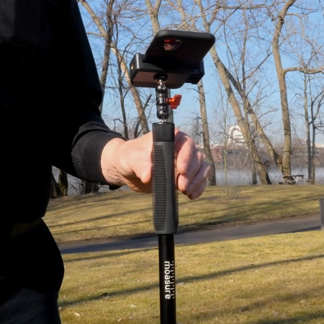
Neste guia aprenderá a mapear um terreno em 3D e a calcular o volume utilizando o Moasure.
O Moasure captura automaticamente as medições em três dimensões, o que facilita o registo das alterações de elevação. A aplicação vai mais além, calculando a área de superfície e o volume, fornecendo-lhe as ferramentas necessárias para medir desde superfícies planas até terrenos complexos.
Para medir o volume com precisão, siga estes passos:
Pode introduzir um código hex.
Ou usar a escala deslizante e o seletor por arrasto.
Clique em Aplicar Cor quando estiver satisfeito com a sua escolha.
Repita os passos 2-4 para novas Camadas.
Clique no X no canto superior direito para sair do Menu de Camadas e voltar ao ecrã principal.


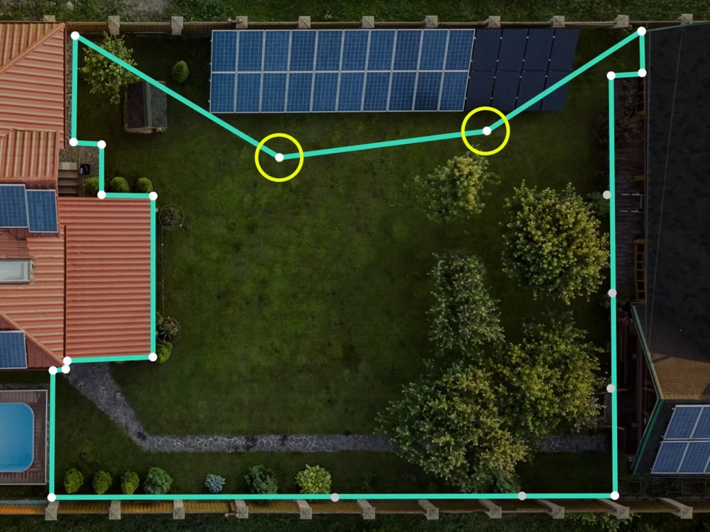
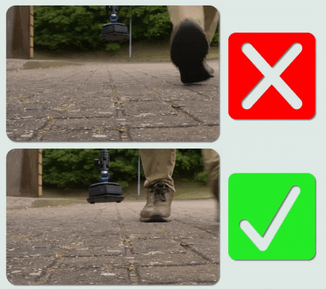


Clique em 'Atualizar'.
Não se esqueça de rodar o dispositivo gradualmente, nunca de forma brusca, e de o colocar no chão de forma rápida mas suave. Caminhe até ao primeiro ponto alvo, certificando-se de que coloca o dispositivo dentro da zona verde da barra de tempo e nunca para além da zona âmbar.
Assim que colocar o dispositivo no terreno, a aplicação indicará se foi colocado dentro do raio do Alvo (previamente definido) ou fora dele. Se o dispositivo estiver fora do raio do Alvo, a aplicação indica-lhe a distância até ao alvo e apresenta uma linha pontilhada entre a sua posição atual e o ponto do alvo, orientando-o na direção correta com uma seta. Se o dispositivo estiver dentro do raio do alvo, o ícone da mira fica verde com uma marca de verificação. Coloque uma estaca o uma bandeira dentro do Alvo. Em seguida, será guiado até ao próximo alvo e assim sucessivamente.
Uma vez atingido o último Alvo, deve regressar ao Ponto de Origem marcado com a letra "A" no plano.


Meça o perímetro.
Volte ao ponto de início sem finalizar a medição.
Altere o Tipo de Rota para 'Pontos'.
Registe pontos de elevação dentro do perímetro. Quanto mais pontos capturar, maior será a precisão no ajuste da superfície. Capture pontos adicionais nas zonas com variações ou irregularidades de elevação.
Quando estiver satisfeito com os pontos capturados, regresse ao ponto de início original (isto melhora a precisão).
Finalmente, clique no botão vermelho para terminar a medição.
O Moasure permite adicionar o volume como uma camada adicional, possibilitando regressar a uma obra mais tarde e medir o volume com base num perímetro previamente registado. Isto é especialmente útil em projetos de paisagismo, colocação de relva ou escavação, onde primeiro se captura a superfície e depois o volume.
Antes de Começar
Certifique-se de que a sua medição original inclui uma linha de orientação formada por dois pontos (A e B) longa e reta.
Marque o Ponto A e o Ponto B com sinais visíveis (como estacas ou cones) para poder voltar facilmente a eles e alinhar a medição.
Como Adicionar uma Camada para Incluir o Volume
Abra a medição guardada e clique em Camadas.
Clique em Adicionar Camada.
Regresse ao Ponto A da Camada Base e caminhe até ao Ponto B da Linha de Orientação.
O Moasure mudará para o modo Ignorar Linha, permitindo-lhe mover-se livremente até ao ponto de início dentro do perímetro (marque-o como Ponto C).
Altere o Tipo de Rota para Pontos e registe pontos de elevação usando um padrão em espiral ou em zig-zag. Utilize mais pontos para superfícies irregulares ou inclinadas.
Volte ao Ponto C para registar o seu ponto final e pressione o ícone vermelho de parar para finalizar a camada.
Para visualizar os resultados, siga estes passos:
Clique no ícone de Superfície 3D para ver os cálculos de volume.
Escolha entre:
Ponto Mais Baixo – usa a elevação mais baixa como base (ideal para escavações).
Perímetro – usa a elevação do bordo exterior como base (ideal para pilhas de material ou áreas elevadas).
Para aceder a mais ferramentas, clique em Editar e depois em:
Corte e Aterro – estima quanto material adicionar ou retirar para nivelar a superfície.
Adicionar Profundidade – calcula o volume sob a superfície, ideal para planear escavações.
Para visualizar as Curvas de Nível, clique no ícone Curvas de Nível. Elas são utilizadas para representar a topografia ou elevação de uma área específica. Normalmente mostram linhas chamadas curvas de nível, que ligam pontos com a mesma elevação. Estas linhas ajudam a visualizar a forma do terreno e a identificar as mudanças de elevação. A distância entre as curvas de nível indica a inclinação: quanto mais próximas estiverem, mais pronunciada é a inclinação e vice-versa. Os intervalos de contorno são configurados automaticamente na aplicação Moasure. Estão disponíveis tanto na vista 2D como 3D, além da possibilidade de editar as configurações das curvas de nível.
Para cálculos mais complexos, como valores de Corte / Aterro ou adicionar material a um terreno, pode utilizar as ferramentas Corte / Aterro e Adicionar Profundidade.
A escolha da ferramenta depende do projeto específico:
Adicionar Profundidade
Está desenhada especificamente para calcular o volume de um material (como mulch, terra ou brita) em função de uma superfície determinada e da profundidade de cobertura desejada.
Multiplicando estes valores, calcula o volume total necessário.
Use esta ferramenta quando precisar calcular o volume para terrenos irregulares, ondulados e/ou inclinados, ou quando for necessário calcular o volume de um material específico (como mulch, terra ou brita) para cobrir uma superfície a uma profundidade definida.
É útil para jardineiros ou paisagistas que planificam a aplicação de mulch e também para profissionais de pavimentação que preparam fundações ou camadas de base para pavimentos ou pátios.
Exemplo: Um paisagista que queira saber quanto mulch adicionar para cobrir um jardim a uma profundidade de 15 cm, ou um profissional de pavimentação que precise criar uma camada base de agregado de 15 cm de profundidade para pavimento ou betão, pode calcular o volume necessário multiplicando a área da superfície por 15 cm. A ferramenta Adicionar Profundidade simplifica este processo, pois pré-calcula a área da superfície e fornece ferramentas (como um controlo deslizante) para especificar a profundidade, resultando no cálculo automático do volume.
Corte / Aterro
Esta ferramenta é utilizada para determinar a quantidade de material que deve ser escavada (corte) ou adicionada (aterro) em projetos de movimentação de terras ou de construção, de modo a atingir os níveis pretendidos e/ou nivelar um terreno.
Use a ferramenta Corte / Aterro em projetos que exijam nivelar o terreno, ajudando a calcular o material que deve ser retirado ou adicionado para alcançar o resultado desejado.
Exemplo: Num projeto de criação de um jardim em socalcos num terreno inclinado, o paisagista pode aplicar técnicas de corte e aterro:
Corte: escavar as zonas mais altas da encosta para criar uma plataforma nivelada para os socalcos do jardim (ex.: retirar 100 m³ de terra).
Aterro: adicionar terra ou outro material de enchimento nas zonas mais baixas, preenchendo os espaços entre os socalcos (ex.: adicionar 100 m³ de material).
Neste caso, os valores de corte e de aterro seriam iguais, resultando num volume líquido de 0. Isto significa que a quantidade de terra retirada (corte) é compensada pela quantidade de material adicionado (aterro), ajudando a criar uma superfície nivelada mantendo o equilíbrio global de volume.
A partir da versão 3.0 da aplicação, as medições de volume podem ser divididas, permitindo que o perímetro seja capturado numa camada e os pontos de elevação noutra, ou que sejam medidas várias camadas de pontos de elevação. Esta flexibilidade com camadas é especialmente útil em terrenos grandes com ondulações significativas.
Principais benefícios da medição multicamada:
Refazer camadas específicas: se ocorrer um erro numa camada, apenas é necessário repetir essa camada em vez de toda a medição.
Melhor resolução: é possível adicionar mais pontos de elevação noutra camada para aumentar a resolução da medição.
Maior flexibilidade: o perímetro pode ser medido numa camada enquanto os pontos de elevação são capturados separadamente.
Possíveis desafios:
Precisão de alinhamento necessária: as camadas devem ser medidas com rigor para garantir uma boa sobreposição e cálculos de volume fiáveis.
Maior risco de erros entre camadas: camadas mal medidas podem provocar desalinhamentos, exigindo uma técnica cuidadosa e validação.
Para mapear com precisão as ondulações do terreno:
Utilize o Tipo de Rota 'Pontos' para registar tantos pontos de elevação quanto necessário, aumentando o detalhe da superfície.
Quanto mais pontos forem registados, mais pequenos serão os triângulos da superfície ajustada, resultando numa maior resolução e num mapeamento de contornos mais realista.
Considere sobrepor camadas de pontos de elevação em terrenos grandes para melhorar a precisão e permitir ajustes ao longo do tempo.
Ao analisar os resultados de uma medição de volume, é essencial compreender como o plano de perímetro e o plano do ponto mais baixo influenciam os cálculos:
Plano de Perímetro: mede o volume total compreendido entre a superfície 3D e uma superfície que apenas intersecta os pontos do perímetro da superfície 3D. É ideal para medir volumes de pilhas de material e outros acúmulos situados em terrenos relativamente planos.
Plano do Ponto Mais Baixo: mede o volume total compreendido num espaço criado ao projetar a superfície 3D verticalmente sobre um plano horizontal com uma elevação igual ao ponto mais baixo da superfície 3D. É ideal para medir volumes de piscinas, tanques e escavações.
Ao tirar partido da adaptação de superfícies em camadas múltiplas, pode aumentar significativamente a flexibilidade e a precisão das medições de volume, especialmente em projetos de mapeamento de terrenos grandes e complexos.


Descubra como montar e utilizar o seu Moasure STICK.
O Moasure STICK é composto pelos seguintes componentes:
Uma caixa revestida a espuma para o seu dispositivo Moasure
Um suporte universal extensível para smartphone
Uma articulação rotativa universal
Um bastão extensível
Um saco de transporte
Fixar a caixa revestida a espuma:
Utilize o parafuso fornecido para fixar a caixa revestida a espuma ao bastão extensível.
Certifique-se de que a parte mais pontiaguda da caixa está virada para cima antes antes de a apertar.
Fixar o suporte universal extensível
Fixe a articulação rotativa universal à parte superior do bastão extensível.
Ligar o suporte para smartphone:
Fixe o suporte universal para smartphone à articulação rotativa universal.
Ajustar o ângulo do suporte para smartphone:
Desaperte o parafuso de ajuste na articulação universal, virando-o no sentido contrário ao dos ponteiros do relógio.
Ajuste o ângulo do suporte do smartphone conforme necessário.
Aperte o parafuso de ajuste virando-o no sentido dos ponteiros do relógio para fixar o suporte.
Inserir o dispositivo Moasure:
Ao inserir o seu dispositivo na caixa almofadada do Moasure STICK, evite segurar o próprio STICK para evitar dobras e tensão na articulação flexível. Em vez disso, vire o STICK de cabeça para baixo e segure a caixa, assegurando que o LED esteja visível.
Certifique-se de que alinha o seu dispositivo Moasure uniformemente dentro da caixa durante a inserção.
O seu Moasure STICK está agora completamente montado e pronto para ser utilizado.
Antes de começar a medir, recomendamos que informe a aplicação Moasure que está a utilizar o Moasure STICK - isto aumentará a precisão.
O do Moasure está localizado na parte mais pontiaguda do dispositivo. Depois de ter informado a aplicação Moasure sobre a utilização do Moasure STICK, o ponto de referência será movido para a ponta da caixa.
Siga estes passos para que a aplicação Moasure saiba que está a utilizar o Moasure STICK:
Vá a Definições (na parte inferior direita do ecrã) na aplicação Moasure;
Clique em Opções de Medição;
Clique na opção Usar o Moasure STICK;
Selecione Sim.
Para utilizar confortavelmente o Moasure STICK, recomendamos que ajuste a altura de modo que a sua mão fique à altura da cintura e o seu antebraço fique na horizontal enquanto caminha. Segure o Moasure STICK entre o polegar e os dois dedos, mantendo uma ligeira aderência.


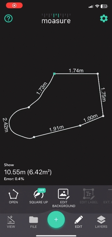
O suporte para smartphone pode ser expandido (compatível com diferentes tamanhos de telemóvel).


A ferramenta Extrapolar Canto extrapola um canto com base nos ângulos dos segmentos da medição. É especialmente útil quando não é possível alcançar fisicamente um canto durante a medição.
Se, por qualquer motivo, não conseguir aceder a um canto durante a medição, pode utilizar a ferramenta Extrapolar Canto após finalizar a medição e o Moasure fará o trabalho por si.
Suponhamos que queremos calcular a área e o perímetro de um jardim, mas não conseguimos chegar a um dos cantos porque existe um obstáculo no caminho.
Capture um mínimo de dois pontos em cada parede/linha antes e depois do canto ao qual não tem acesso e que pretende extrapolar.
Selecione a linha que pretende extrapolar até ao canto.
Clique em 'Editar' e, em seguida, selecione 'Extrapolar Canto'.
Esta ação extrapolará a linha selecionada até ao canto, completando automaticamente a medição.
Nesta guia irá aprender como exportar medições, para que formatos as pode exportar e que opções de configuração pode escolher para personalizar os ficheiros exportados.
O Moasure permite adicionar , o que lhe possibilita regressar a uma obra mais tarde e medir o volume com base num perímetro previamente registado. Isto é especialmente útil em projetos de paisagismo, colocação de relva ou escavação, onde primeiro se captura a superfície e depois o volume.
Certifique-se de que a sua medição original inclui uma linha de orientação formada por dois pontos (A e B) longa e reta.
Marque o Ponto A e o Ponto B com sinais visíveis (como estacas ou cones) para poder regressar facilmente a eles e alinhar a medição.
Recomenda-se também marcar o ponto inicial da área de superfície (Ponto C), para que possa regressar à mesma posição ao capturar os dados de volume.
Abra a medição guardada e clique em Camadas.
Clique em Adicionar Camada.
Regresse ao Ponto A da Camada Base e caminhe até ao Ponto B da Linha de Orientação.
O Moasure mudará para o modo Ignorar Linha, permitindo-lhe deslocar-se livremente até ao ponto de início dentro do perímetro (marque-o como Ponto C).
Altere o Tipo de Rota para Pontos e capture pontos de elevação usando um padrão em espiral ou em zig-zag. Tome mais pontos em superfícies irregulares ou inclinadas.
Regresse ao Ponto C para capturar o ponto final e pressione o ícone vermelho para finalizar a camada.
Clique no ícone de Superfície 3D para ver os cálculos de volume.
Escolha entre:
Ponto Mais Baixo – utiliza a elevação mais baixa como base (ideal para escavações).
Perímetro – utiliza a elevação do limite exterior como base (ideal para pilhas de material ou áreas elevadas).
Ferramentas Avançadas (Menu Editar)
Para aceder a ferramentas adicionais, clique em Editar e depois em:
Corte e Aterro – estima quanto material é necessário adicionar ou remover para nivelar a superfície.
Adicionar Profundidade – calcula o volume sob a superfície, ideal para planear escavações.

DXF (Drawing Exchange Format): para utilização em programas CAD.
DWG (Drawings): para utilização em programas CAD.
CSV (Comma-Separated Values): para visualizar as coordenadas em bruto numa folha de cálculo.
Imagem: pode exportar nos formatos PNG, JPG ou SVG.
Ficheiro MFile: pode exportar em MFile para partilhar com outra aplicação Moasure.
Abra a aplicação Moasure e selecione a medição que pretende exportar, clicando em Arquivos na parte inferior da aplicação e depois em Medições.
Uma vez carregada a medição, clique em Arquivos > Exportar.
Selecione o formato de exportação pretendido entre as opções disponíveis.
Ao exportar para PDF, pode alterar as opções de configuração predefinidas para personalizar o documento conforme a sua conveniência. É possível pré-visualizar como as opções afetam o PDF antes da exportação, clicando em Mostrar Pré-visualização na parte inferior da aplicação.
Tamanho da Fonte: define o tamanho do texto utilizado em todo o documento PDF.
Formato do Papel: o formato de papel para o qual será exportado o PDF. Pode escolher entre uma vasta gama de opções, incluindo de A0 a A4, bem como formatos de engenharia como ANSI C a E.
Orientação do Papel: escolha entre vertical ou horizontal.
Ajustar Desenho à Página: esta opção vem selecionada por defeito.
Reduz ou aumenta automaticamente a medição para se ajustar às dimensões do papel escolhido.
Se o conteúdo for maior que o tamanho do papel selecionado, será reduzido proporcionalmente para caber no espaço disponível.
Se for menor, poderá ser aumentado proporcionalmente para maximizar a utilização da página, evitando que apareça demasiado pequeno em formatos maiores.
Escala Predefinida: disponível ao desativar a opção Ajustar Desenho à Página.
Permite escolher entre várias escalas, de 1:1 a 1:500.
Cada exportação com escala definida (seja ajuste automático ou escala predefinida) apresenta uma barra de escala que indica a relação entre as medidas representadas no papel e as medidas reais.
Exemplo:
Escala 1:5 → cada unidade no papel (1 cm) representa 5 cm na realidade.
Se medir uma linha de 4 cm no papel, a medida real será de 20 cm (4 × 5 = 20).
Além disso, atrás da medição aparece uma grelha de quadrados que pode ser usada para estimar dimensões no mundo real. Esta grelha serve como referência visual para avaliar proporções e tamanhos relativos dentro da medição.
Lembre-se: os valores reais das linhas de medição estão sempre disponíveis no PDF.
A seguir pode descarregar um exemplo de PDF exportado com a opção Ajustar Desenho à Página ativada.
Centrar na Página: A opção Centrar na Página vem selecionada por defeito e centra a medição na página, mesmo quando a medição é arrastada para a esquerda ou para a direita no espaço de trabalho da aplicação antes de ser exportada. Se esta opção estiver desativada, a medição não será centrada. Isto pode ser útil quando pretende exportar apenas uma seção da medição (a seção que está visível no espaço de trabalho da aplicação). Abaixo pode ver exemplos do mesmo PDF com a opção Centrar na Página ativada e desativada.
Mostrar Grade: esta opção vem selecionada por defeito. Exibe uma grade clara no PDF.
Mostrar Camadas em Páginas Separadas: também selecionada por defeito. Quando ativada, apresenta as camadas (em medições por camadas) no PDF, representando cada camada em páginas distintas.
Mostrar Imagem de Fundo: selecionada por defeito. Quando ativada e se adicionar uma imagem de fundo à medição através da ferramenta Editar Fundo, a imagem de fundo será incluída no PDF.
Mostrar a Preto e Branco: permite exportar o PDF em preto e branco em vez das cores predefinidas. É útil para obter maior contraste ou simplesmente para poupar tinta.
A partir da versão 3.0 da aplicação, as medições de Ponto a Ponto podem ser exportadas para PDF com escala, garantindo uma representação precisa para utilização em apresentações, relatórios ou processamento posterior.
Complete a medição utilizando o tipo de medição Ponto a Ponto.
Clique em Arquivos.
Clique em Exportar.
Clique em PDF.
Configure o PDF de acordo com as suas preferências.
Clique em Mostrar Pré-visualização.
Clique em Exportar.
Escolha onde enviar o PDF ou guarde-o nos seus ficheiros.
O PDF será gerado com um plano à escala.
A exportação para CAD permite gerar medições nos formatos DWG, DXF e DXF (Versão antiga). Isto garante compatibilidade com programas CAD e assegura um intercâmbio de dados fiável e padronizado.
Complete a medição na aplicação.
Clique em Exportar e selecione CAD.
Clique em Formato e escolha entre DXF, DWG ou DXF (Versão Antiga).
Selecione a Vista preferida:
Plano (2D)
3D
Curvas de Nível (3D)
Superfície (3D)
Clique em Ignorar Pontos e selecione Mostrar ou Ocultar.
Se mostrar, os pontos ignorados serão incluídos numa camada específica dentro do ficheiro CAD, facilitando a sua diferenciação em relação aos restantes pontos.
Clique em Etiquetas e selecione Mostrar ou Ocultar, para decidir se quer incluir etiquetas nos pontos da exportação.
Clique em Anotações e selecione Mostrar ou Ocultar, para decidir se quer incluir anotações no plano exportado.
Clique em Exportar na parte inferior do ecrã para gerar o ficheiro CAD.
Ao exportar para DXF ou DWG, pode escolher entre duas opções:
3D: inclui dados de elevação.
2D: achata os dados, eliminando a elevação.
Ao exportar para imagem, pode escolher entre três formatos:
PNG
JPG: ideal para tamanhos de ficheiro otimizados.
SVG: ideal para fundos transparentes.
Ao exportar para CSV, pode alterar as opções de configuração predefinidas para personalizar o ficheiro de acordo com a sua conveniência.
A seguir apresentam-se as diferentes opções de configuração disponíveis:
Mostrar Número da Rota: adiciona uma coluna e um valor para o número do tipo de rota do ponto registado. O número corresponde à ordem dos tipos de rota na medição.
Exemplo: o primeiro tipo de rota medido será o número 1.
Se, de seguida, alterar o tipo de rota (por exemplo, de Linha Reta para Traçar), o novo número de rota será 2.
Se utilizar apenas um tipo de rota durante toda a medição, todos os pontos terão o número 1.
Mostrar Tipo de Rota: adiciona uma coluna e um valor para o tipo de rota do ponto registado.
Os tipos de rotas no ficheiro CSV nem sempre coincidem com os valores apresentados na interface da aplicação.
É fornecida uma tabela de correspondência para ajudar a compreender o significado dos valores no CSV.
Dot2Dot
SmoothTrace
Traçar (com a opção )
Trace
LastLeg
A linha tracejada que, por vezes, é adicionada pela ferramenta .
Null
Mostrar Etiqueta do Ponto: adiciona uma coluna e um valor para a etiqueta do ponto registado, adicionada através da ferramenta Editar Etiqueta.
Mostrar Tipo de Ponto: adiciona uma coluna e um valor para o tipo de ponto registado (por exemplo, por defeito, Ponto de Voo). Um tipo de ponto pode ser um dos seguintes:
Default
Este é um ponto de pausa normal.
IgnorePoint
Este é um ponto normal de ignorar.
FlightPoint
Trata-se de um ponto de amostra exato num Traçado ou Traçado Suave.
CenterPoint
Trata-se de um ponto localizado no centro de um Arco/Círculo.
ArcPoint
Trata-se de um ponto numa Trajetória de Arco/Círculo.
Mostrar Nome da Camada: adiciona uma coluna e um valor para o nome da camada em que se encontra o ponto registado (por exemplo, Camada Base).
Mostrar Número da Camada: adiciona uma coluna e um valor para o número da camada. O número corresponde à ordem cronológica em que as camadas são adicionadas.
Exemplo: se adicionar uma nova camada à sua medição, haverá duas camadas no total.
A primeira camada (Camada Base) será o número 1 e a segunda camada (adicionada) será o número 2.
Mostrar Cabeçalho da Coluna: adiciona nomes de cabeçalho de coluna na primeira linha.
Mostrar Área: adiciona uma coluna e um valor para a área.
Mostrar Pontos Ignorados: inclui os pontos ignorados no CSV.
Usar Formato Local: aplica o formato numérico local para apresentar os valores.
Exemplo: se estiver ativado, um utilizador do Reino Unido verá o valor formatado como 150.65, enquanto um utilizador de Portugal verá o mesmo número formatado como 150,65.
A seguir apresentamos uma captura de ecrã de um ficheiro CSV exportado diretamente da aplicação Moasure. Também pode descarregar um ficheiro CSV de exemplo.
Não existem opções de configuração para ficheiros MFile.
Para além de exportar ficheiros de forma individual, também pode exportar vários ficheiros em simultâneo. Para isso, siga estes passos:
Clique em Arquivos > Exportação Múltipla.
Selecione os ficheiros que pretende exportar ou escolha uma pasta de projeto.
Selecione o formato para o qual deseja exportar os ficheiros.
A ferramenta Etiquetas permite adicionar texto aos pontos do plano. Isto possibilita referenciar facilmente qualquer ponto de interesse no desenho, de forma rápida e prática, sem necessidade de criar camadas adicionais.
Além de poder fazer Anotações no plano, também tem a possibilidade de adicionar Etiquetas aos pontos de pausa enquanto mede, ou depois de concluir a medição.
Sempre que o seu dispositivo Moasure permanece imóvel após se deslocar, é registado um ponto de pausa. Quando parar no primeiro ponto de pausa, aparecerá um ícone de lápis no ecrã.
Quando estiver parado num ponto de pausa, clique no ícone do lápis.
Clique no ícone do microfone.
Diga em voz alta o nome da etiqueta enquanto permanece imóvel.
Clique novamente no ícone do microfone para parar a gravação — ou continue a medição, e a gravação de voz será interrompida automaticamente.
A etiqueta será adicionada ao ponto de pausa mais recente.
O ponto de pausa etiquetado ficará a laranja no espaço de trabalho.
Quando estiver parado num ponto de pausa, clique no ícone do lápis.
Clique no ícone de texto.
Escreva o nome da etiqueta na caixa de texto.
Clique em 'Aplicar' para confirmar ou em 'Cancelar' para descartar a etiqueta e voltar à medição.
Também pode adicionar etiquetas depois de concluir a medição. Para isso, siga estes passos:
Abra uma medição.
Clique no ponto que deseja etiquetar.
Clique em 'Editar'.
Clique em 'Adicionar Etiqueta'.
Para eliminar uma etiqueta existente, siga estes passos:
Clique num ponto etiquetado no plano para o selecionar.
A etiqueta aparecerá com um ícone de caixote do lixo ao lado.
Clique no ícone de caixote do lixo para eliminar a etiqueta.

A etiqueta será aplicada automaticamente ao ponto de pausa atual, a menos que tenha selecionado previamente um ponto de pausa anterior antes de clicar no botão 'Etiqueta'.
O ponto de pausa etiquetado ficará a laranja no espaço de trabalho.
Clique em 'Aplicar'.
Verá que a etiqueta aparece no ecrã. Clique em qualquer outro local da medição para ocultar a etiqueta.
O ponto etiquetado permanece visível e é identificado pela cor laranja.
WallPoint
Este é um ponto no tipo de rota 'Parede'.


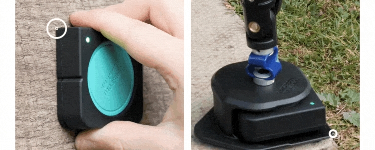
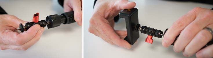
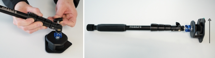
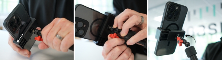
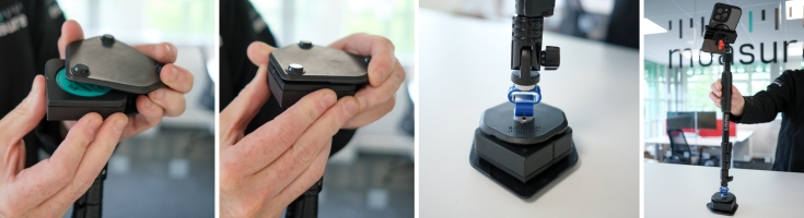
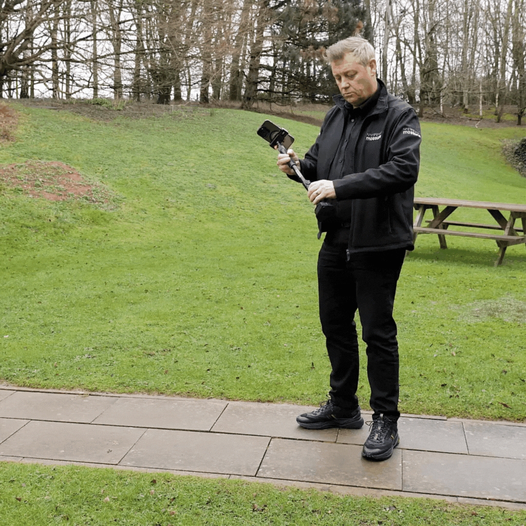
Quando iniciar uma medição na aplicação Moasure, utilizará um Tipo de Rota, que é a forma como dois pontos são ligados. O Moasure oferece sete tipos de rotas diferentes, cada um adequado para um tipo específico de medição ou ambiente.
Pode mudar o tipo de rota em qualquer ponto de pausa, seja durante a medição ou depois de a ter concluído. Isto permite-lhe adaptar-se a diferentes formas, obstáculos e características dentro de um mesmo projeto.
Selecionar o tipo de rota correto garante medições mais precisas, especialmente ao trabalhar com superfícies curvas, alterações de elevação ou desenhos complexos.
Para iniciar uma medição, abra a aplicação Moasure e clique no ícone verde +.
Escolha entre os 'Forma Fechada' ou 'Forma Aberta'.
Uma vez selecionado, o ícone de 'Rotas' aparecerá na parte inferior do ecrã, mostrando os sete tipos de rotas disponíveis.
Enquanto estiver num ponto de pausa, sempre que o dispositivo Moasure estiver imóvel, pode permanecer em pausa o tempo que precisar antes de avançar para o ponto seguinte.
Se começar a deslocar-se a partir de um ponto de pausa, o tipo de rota atual permanecerá ativo até que o altere manualmente, selecionando o mais adequado para a medição seguinte.
Ao iniciar uma nova medição, começará com o tipo de rota predefinido: Linha Reta — embora possa modificar o nas definições da aplicação.
O tipo de rota Linha Reta é o mais utilizado. Liga dois pontos de pausa através de uma linha reta, independentemente do percurso real seguido.
Este tipo de rota é ideal para:
Medir distâncias diretas
Contornar obstáculos como árvores, rochas ou móveis de jardim
Manter as medições rápidas, simples e precisas
Linha Reta é o tipo de rota predefinido ao iniciar uma nova medição, embora possa alterar o tipo de rota nas definições da aplicação a qualquer momento.
O tipo de rota Traçar regista o movimento preciso do dispositivo Moasure entre os pontos de pausa. É ideal para formas complexas, curvas ou irregulares, como , e lagos/estanques.
O tipo de rota Pontos captura pontos individuais sem os ligar através de linhas. É especialmente útil para marcar locais de interesse, como árvores ou aspersores. Também é o tipo de rota necessário para registar pontos de elevação ao medir volumes.
Métodos para utilizar o tipo de rota 'Pontos' em cálculos de volumes
1. Durante uma medição contínua:
Comece por capturar o perímetro.
Regresse ao ponto inicial sem finalizar a medição.
Mude para o tipo de rota 'Pontos' para registar as alterações de elevação dentro da área.
Para recolher dados de elevação em toda a superfície:
2. Como camada separada:
Primeiro, complete a medição do perímetro.
Em seguida, percorra novamente a linha de referência formada pelos pontos A e B () para garantir o alinhamento.
Ao atingir o ponto B, o Moasure mudará automaticamente para o tipo de rota 'Ignorar Linha'.
Independentemente do método escolhido, cada ponto regista as coordenadas X, Y e Z, garantindo um mapeamento preciso da elevação.
O tipo de rota 'Ignorar Linha' permite omitir um comprimento ou distância na sua medição. Por exemplo, se quiser omitir um lado ou segmento de uma medição perimetral, basta mudar o tipo de rota para 'Ignorar Linha' e poderá continuar a medição; no final, o lado ignorado não aparecerá no plano.
Por outro lado, se quiser medir em redor de um obstáculo mas ainda assim registar o movimento no plano, utilize antes o tipo de rota 'Linha Reta'. Os pontos serão ligados por uma linha reta, mesmo ao contornar o obstáculo.
O tipo de rota Parede foi concebido para capturar o perímetro de estruturas exteriores com muros, como blocos de escritórios ou habitações.
Como utilizá-lo:
Coloque o dispositivo Moasure, sem o STICK, no centro de cada parede, com a luz LED virada para cima (canto superior esquerdo).
A aplicação capturará o plano da parede e determinará automaticamente os cantos, ajudando-o a mapear o espaço com precisão.
Para garantir a maior precisão, deve terminar a medição no mesmo ponto em que começou. Isto gera um diagrama completo, mostrando o perímetro e a área, facilitando a planificação de alterações ou a avaliação do espaço disponível.
Se encontrar uma parede bloqueada por árvores, vedações ou móveis, pode contorná-la facilmente utilizando o tipo de rota 'Ignorar Linha'.
Em vez de parar a medição, coloque o dispositivo Moasure plano no chão, com o logótipo e a luz LED virados para cima.
Desta forma, o Moasure mudará automaticamente para 'Ignorar Linha' e esse ponto será omitido.
De seguida, contorne o obstáculo e volte a colocar o dispositivo na vertical contra a mesma parede para retomar a medição.
O Moasure continuará exatamente onde tinha parado, mantendo a medição precisa e completa.
Este método é especialmente útil para medir edifícios ou espaços com áreas de difícil acesso, garantindo que toda a estrutura é capturada sem interrupções.
O tipo de rota Arco é utilizado para medir formas curvas, como entradas, piscinas ou caminhos sinuosos.
Para capturar um arco, registe pelo menos três pontos: um no início, outro no meio e outro no final da curva. A aplicação Moasure traça primeiro uma linha reta até ao segundo ponto e, em seguida, ajusta o arco até ao terceiro.
Para formas mais complexas, como uma curva em 'S', pode combinar os tipos de rota Arco e Linha Reta:
Capture o arco inicial tomando três pontos.
Altere para o tipo de rota 'Linha Reta' para adicionar um pequeno segmento entre as curvas — isto indica à aplicação que um novo arco vai começar, evitando que a rotação do arco anterior continue.
Altere novamente para o tipo de rota 'Arco' para medir a segunda curva, registando três pontos (início, meio e fim).
Com ambos os arcos e o segmento reto, a forma em 'S' ficará completa.
O tipo de rota Círculo gera automaticamente o círculo com melhor ajuste com base nos pontos registados.
Para capturar uma forma circular, tome pelo menos três pontos em torno da circunferência, dispostos em triângulo em vez de regressar ao ponto inicial. Isso ajuda a definir a forma com maior precisão.
Para áreas circulares maiores, como uma rotunda, um largo ou uma praça circular, registar quatro ou mais pontos ao longo da borda aumenta a precisão e garante uma medição mais exata em formas circulares grandes e bem definidas.
Embora o número mínimo de pontos de pausa exigido para as rotas Arco e Círculo seja três, capturar um ou mais pontos adicionais (quatro ou mais no total) resultará numa medição mais precisa.
Se desejar, pode mudar o Tipo de Rota depois de concluir a medição:
Clique em 'Editar'.
Vá até 'Editar Rotas'.
Selecione a seção correspondente no desenho.
Clique em 'Mudar Tipo de Rota' e escolha o tipo desejado.
Em áreas ovais ou circulares, utilize um padrão em espiral para manter consistência na técnica.
Em áreas retangulares ou quadradas, utilize um padrão em zig-zag para assegurar uma cobertura uniforme e a máxima precisão.
Mais uma vez:
Para áreas ovais ou circulares, utilize um padrão em espiral.
Para áreas retangulares ou quadradas, o padrão em zig-zag proporciona maior precisão.
Clique em 'Salvar' para aplicar as alterações.
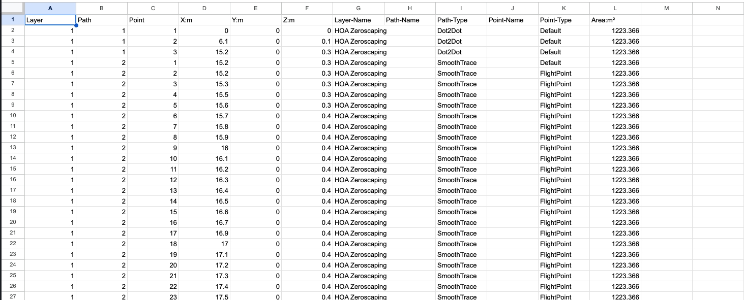


A função de Camadas permite-lhe capturar várias áreas numa mesma medição, oferecendo-lhe um desenho completo e delimitado de todas as formas, posicionadas umas em relação às outras.
Esta seção inclui:
Como funciona a função de Camadas
Instruções Passo a Passo para criar Camadas
Conselhos chave para a precisão e a repetibilidade
Utilização de medições de Formas Fechadas e Formas Abertas
A possibilidade de capturar várias áreas ou formas dentro de uma mesma medição é possível graças à definição da primeira linha (ou linha de orientação). Esta linha inicial atua como referência ou linha base, garantindo a colocação precisa das formas seguintes dentro da medição global.
Ao escolher a linha inicial (ou de orientação), tenha em conta três fatores-chave:
Comprimento: quanto mais longa for a linha de orientação (ponto inicial e ponto seguinte), menor será o impacto do erro humano na medição. Caminhe rapidamente de um ponto para outro, tentando parar exatamente quando a barra de tempo passar da zona verde para a zona âmbar. Mantenha uma trajetória fluida e constante ao caminhar, pois isso melhora a precisão do dispositivo Moasure ao posicionar cada camada em relação às restantes.
Distintividade e repetibilidade: selecione uma linha claramente reconhecível e fácil de repetir. Para maior clareza e simplicidade, recomenda-se escolher uma linha longa e reta utilizando o tipo de rota 'Linha Reta'.
Localização: coloque a sua primeira linha numa posição central dentro da área total da medição. Isto reduz a distância necessária a percorrer para cada camada adicional.
Ao capturar camadas adicionais, deve regressar à linha de orientação (primeiros dois pontos da Camada Base) para que o Moasure possa determinar a posição relativa da nova camada. Manter esta linha inicial numa posição central maximiza a precisão, pois minimiza a distância de deslocação entre diferentes áreas.
Clique no ícone '+' na parte inferior central do ecrã para iniciar uma medição.
Selecione 'Forma Fechada' na lista de opções de medição disponíveis.
Escolha o 'Tipo de Rota' com que pretende começar a medição. Recomenda-se 'Linha Reta' para capturar a linha de orientação (lembre-se de que pode mudar para outros tipos de rotas em qualquer ponto de pausa durante a medição).
Certifique-se de que a sua primeira medição (Ponto A e Ponto B) é longa e não se esqueça de caminhar rapidamente dentro do intervalo de tempo habitual.
Importante: Os dois primeiros pontos capturados no início da medição serão usados como 'Pontos de Referência' para as restantes Camadas. Isto garante que fiquem corretamente sobrepostas.
Importante: Lembre-se de salvar as suas medições em 'Arquivos' > 'Salvar' para manter a medição com camadas. Tenha em conta que 'Salvar' apenas armazena o ficheiro atual.
Se pretender manter a medição original sem alterações e salvar a nova medição (que agora inclui a Camada Base e a Camada Adicional) como um ficheiro independente, selecione 'Guardar Como Cópia'.
Por favor, certifique-se de que a linha de orientação seja de fácil acesso e localização, já que, sempre que criar uma nova Camada, terá de regressar a ela.
Idealmente, a linha de orientação deve ter um comprimento entre 6 e 8 metros.
Ao iniciar uma nova camada, irá reparar que o Tipo de Rota é definido automaticamente como 'Ignorar Linha'. Isto impede que a linha de orientação apareça no plano.
Assim que se deslocar da linha de orientação até ao primeiro ponto da nova camada e estiver pronto para medir, altere de 'Ignorar Linha' para o Tipo de Rota que pretende utilizar (Linha Reta, Traçar, Arco, Círculo, etc.).
Quando estiver pronto para finalizar a sua segunda camada, clique no botão vermelho situado na parte inferior central do ecrã.
Todas as camadas devem partilhar os mesmos dois primeiros pontos de referência para garantir que ficam corretamente sobrepostas.
Ao adicionar uma nova Subcamada, a rota entre a linha de orientação e o primeiro ponto da Subcamada será automaticamente definida como 'Ignorar Linha', o que significa que essa linha não aparecerá no plano.
Assim que chegar à Subcamada e estiver pronto para começar a medir, altere o Tipo de Rota para desenhar no plano.
Pode alternar entre Tipos de Rotas durante a medição em qualquer ponto de pausa.
O Moasure permite medir ao trabalhar com Camadas. No entanto, o comportamento do fecho depende da forma inicial medida na Camada Base:
Se começar com uma Forma Fechada na Camada Base, todas as camadas seguintes serão tratadas como formas fechadas.
Se começar com uma Forma Aberta na Camada Base, as camadas seguintes seguirão esse padrão de forma aberta.
Se medir uma forma aberta (ou seja, não terminar no mesmo ponto de início), o Moasure ligará automaticamente os pontos finais com uma linha tracejada para 'fechar' a forma, exceto se esta consistir apenas em dois pontos que formam uma linha reta. Tem ainda a opção de reabrir a forma mais tarde, caso seja necessário. É importante ter em conta estes comportamentos para garantir medições precisas e consistentes ao utilizar a função de Camadas do Moasure.
Quando estiver pronto para finalizar a sua primeira medição (Camada Base), clique no botão vermelho na parte inferior central.
Para criar uma segunda Camada, clique no ícone 'Camadas' no canto inferior direito e selecione 'Adicionar Camada'.
Para adicionar novas Camadas, consulte o Ponto 6 das instruções anteriores.
Lembre-se de que o erro de medição aumenta com o tempo, e não com a distância.
Faça uma pausa a cada 6-8 segundos entre pontos.
Procure manter um ritmo de pelo menos 1 metro por segundo; faça pausas mais frequentes em medições mais longas. Aproveite cada pausa para planear o movimento seguinte.
Utilize a ferramenta 'Ignorar Pontos' da aplicação para 'ignorar' pontos individuais capturados durante a medição.
Se ignorar um ponto do plano, a aplicação ligará o ponto anterior ao seguinte através de uma linha.
Use esta função quando precisar de contornar um obstáculo ou quando não tiver linha de visão através dele.
Clique no Instrutor do Moasure (canto superior esquerdo da aplicação) ao terminar uma medição para ver sugestões de melhoria (caso existam).

